H&K PSG1 · Volume 3
How It Works: Roller-Delayed Blowback Tuned for Precision
The full cycle part by part in H&K's and the Bundeswehr's own words, the 1:4 ratio, the fluted chamber, the closing aid, the trigger, and the PSG1's departures from the G3
The PSG1 works exactly as a G3 works. H&K’s booklet says so, its one-page description of the cycle is a G3 description, and the Bundeswehr’s G3 regulation explains the same cycle with more numbers.12 What the PSG1 changes is everything around the cycle: barrel, receiver stiffness, trigger, closing, stock and sight. This volume describes the cycle first, from the primary documents, and then each PSG1 change, with a note of how well each is sourced. The roller-delayed lineage (Mauser, CETME, G3) is in Volume 1 and is not repeated.
3.1 Sources for this volume
Table 1 — Sources for this volume
| Source | Status | Used for |
|---|---|---|
| H&K, Kurzbeschreibung des Präzisionsschützengewehres PSG 1 | Factory booklet, H&K copyright | The PSG1’s parts, its cycle text, closing aid, trigger, barrel, data |
| ZDv 3/13, Das Gewehr G3 (Bundeswehr, 1978/1999) | Public domain per Commons | The cycle with the 1:4 ratio; drawings |
| H&K, Technical Description of the Automatic Rifle HK G3 (English) | H&K-derived, copyright | Bolt parts, 12 flutes, bolt gap, firing-pin protrusion, “1:4” |
| US patents assigned to Heckler & Koch, 1966–1973 | Public domain | Drawings of the roller breech, anti-rebound lever, polygon barrel, chamber grooves |
Secondary sources (Forgotten Weapons, The Firearm Blog, Sniper Central, Modern Firearms, Deutsches Waffen-Journal) are used only for PSG1-specific details that no primary document covers, and are attributed where used.
3.2 The names of the parts
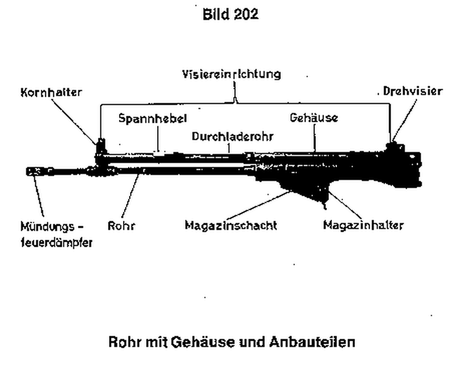
The German names matter because they are H&K’s, and the English ones vary between translations.
Table 2 — The names of the parts
| H&K German (PSG1 booklet, ZDv) | H&K English (G3 description, HK91 leaflet) | What it does |
|---|---|---|
| Verschlußträger | bolt head carrier | The heavy part of the bolt; carries the recoil-spring tube |
| Verschlußkopf | bolt head | Carries the bolt face, the extractor and the two rollers |
| Verschlußrollen, Verriegelungsrollen | locking rollers | Sit between the head and the trunnion |
| Steuerstück | locking piece (also translated control piece) | The wedge between the rollers; rides in the carrier |
| Verriegelungsstück | barrel extension | The trunnion: carries the roller recesses; the barrel is pressed into it |
| Abstützflächen | (support faces) | The angled faces of the trunnion recesses the rollers bear on |
| Sperrhebel | check lever, bolt head locking lever | Spring lever on the carrier that holds the head against rebound |
| Schlagbolzen, Schlagbolzenfeder | firing pin, firing pin spring | |
| Auszieher | extractor | |
| Durchladerohr, Spannhebel (Ladehebel on the PSG1) | loading lever housing, cocking lever | The cocking tube above the barrel and its handle |
| Schließfeder | recoil spring | In the end cap, driving the bolt forward |
| Entlastungsrillen | chamber flutes, chamber grooves | Lengthwise grooves in the chamber |
| Schließhilfe | low noise bolt closing aid | PSG1 and MSG90 only |
To avoid a clash between “locking piece” (H&K’s English for the Steuerstück) and “locking piece” (the literal English for the Verriegelungsstück), this dive calls the first the control piece and the second the trunnion throughout.
3.3 Why a rifle cartridge cannot simply blow the bolt back
A blowback action holds its bolt closed only by mass and spring. At the moment of firing, gas pressure inside the case pushes the case head rearward against the bolt face, and also expands the case outward against the chamber wall. With a pistol cartridge the bolt can be made heavy enough that it barely moves before the bullet leaves the muzzle. With a full-power rifle cartridge the bolt would have to be impossibly heavy; and if it is not, it starts back while pressure is still high, and the case, pressed against the chamber wall, is pulled apart.
Edward Stecke’s American patent of 1934 stated the problem in one sentence: “the frictional resistance of a non-lubricated cartridge case relatively to the barrel chamber at the moment of maximum pressure in the chamber, is greater than the pressure on the bottom of the cartridge.”3 Roller-delayed blowback is H&K’s answer to both halves of that sentence. A mechanical delay keeps the bolt head almost still during peak pressure without locking it, and the fluted chamber stops the case from gripping (below).
3.4 The cycle in H&K’s words
The PSG1 booklet’s own description of the cycle, Zusammenwirken der Teile (“how the parts work together”), is short and is given here in full translation, because it is H&K’s only published statement of how the PSG1 works:1
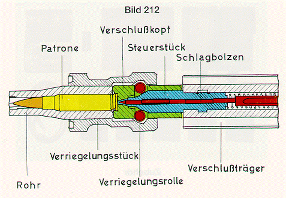
“The weapon is loaded and the safety off. Pulling the trigger releases the hammer, which strikes the firing pin. The cartridge is fired. The powder gases drive the bullet. At the same time the powder gases press on the cartridge case. The forces acting on the face of the bolt head are transmitted through the bolt rollers partly to the receiver and partly, through the control piece, to the bolt carrier, the matched angles of the control piece and the trunnion producing a delayed rearward movement of the bolt head. This ensures that the bolt closes the barrel until the bullet has left the muzzle.
“Once the bolt rollers have entered the bolt head completely, the bolt can slide on to the rear. The cartridge case is ejected and the hammer cocked again. The recoil spring, compressed at the same time, brings the bolt forward again. The cartridge is fed from the magazine into the chamber. The extractor engages the extractor groove of the case. The bolt rollers are pressed by the inclined faces of the control piece onto the support faces of the trunnion. The weapon is ready to fire again.”
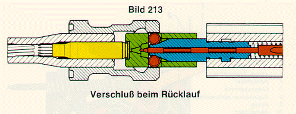
The booklet’s sectional drawings (its Bild 28 and 29, not reproduced here because they are H&K’s copyright) label the cartridge, bolt head, control piece, firing pin, barrel, trunnion, roller and carrier, and on the second drawing the Entlastungsrillen, the flutes in the chamber, and the Abstützflächen, the trunnion’s support faces. The Bundeswehr’s drawings of the G3 show the same parts and are used below.
3.5 The cycle step by step
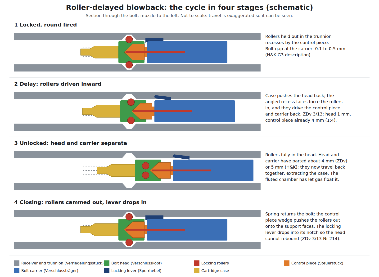
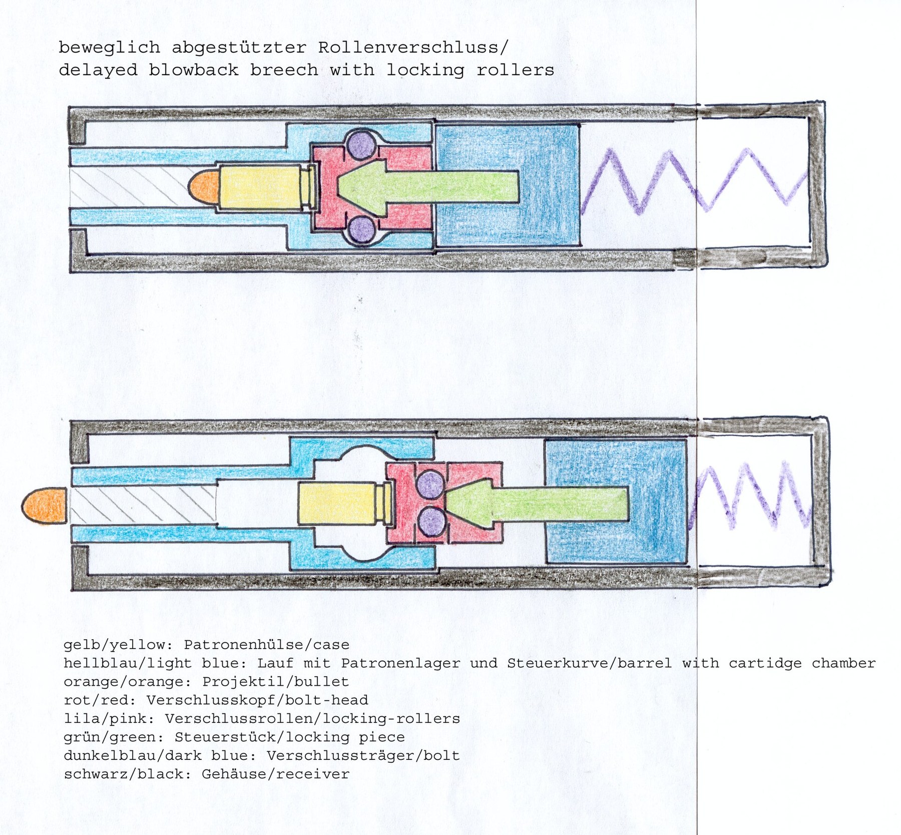
1. Locked. With the bolt forward, the control piece’s wedge-shaped nose sits between the two rollers and holds them out of the bolt head, into recesses in the trunnion. The rollers bear on the recesses’ angled support faces. Nothing is locked in the sense that a rotating bolt is locked: the rollers are held out only by the control piece, and the control piece only by the carrier’s inertia and the recoil spring.2
2. The delay. Firing pushes the case head back against the bolt face. The bolt head cannot move straight back, because the rollers would have to pass through the trunnion’s support faces. Instead, as pressure builds, the angled faces force the rollers inward, and the rollers, moving inward, push on the control piece’s inclined faces and drive it rearward. The control piece is held in the carrier, so the carrier is driven rearward too, faster than the head. The Bundeswehr regulation’s instructor’s note:
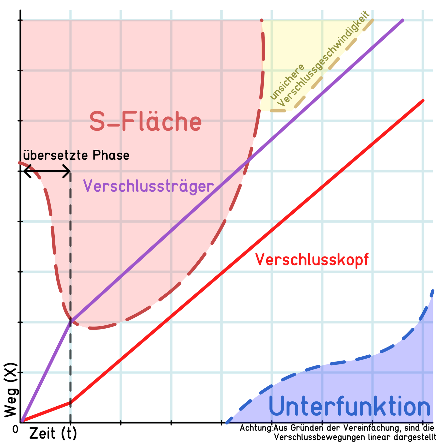
“The locking rollers, at first still pressed outward by the control piece, prevent the immediate recoil of the bolt head. Only after pressure has built up on the inclined faces of the trunnion are the locking rollers forced inward, pressing the control piece rearward over its inclined faces. This gives a transmission ratio of 1:4; that is, when the bolt head has gone back 1 mm, the control piece has already travelled 4 mm.”2
3. Unlocking and separation. As the carrier moves back it pushes the locking lever out of its notch in the bolt head (below). The head and carrier separate: “Bolt head and bolt carrier separate by about 4 mm,” says the Bundeswehr; H&K’s G3 description says “to a distance of about 5 mm”. The two figures are given separately here because they are not the same.24 “These two delays,” the regulation continues, meaning the roller delay and the separation, “are necessary to prevent premature unlocking of the bolt while the bullet is still in the barrel.”2
4. Recoil. Once the rollers are fully inside the head, the whole bolt travels back together, extracting the case, which is thrown out to the right when it strikes the ejector, and cocking the hammer. The bolt is stopped by the buffer in the end cap.14
5. Return and closing. The compressed recoil spring drives the bolt forward. The bolt head strips a round from the magazine and chambers it; the extractor snaps over the rim. The carrier, still moving forward after the head has stopped against the breech, drives the control piece’s wedge between the rollers and forces them out onto the trunnion’s support faces. At that moment the locking lever drops into its notch in the head (below). The rifle is ready to fire again.21
3.6 The 1:4 ratio, and what it is a ratio of
The 1:4 figure is quoted in almost every account of the G3, often as “the carrier moves four times faster than the head”. The primary sources say it in two different ways:
- H&K’s G3 description: “the bolt head carrier … is activated by means of the locking rollers … and the locking piece … in the proportion 1:4”.4 It does not say whether 1:4 is head to carrier or carrier to head, nor whether it is distance or speed.
- The Bundeswehr regulation: “when the bolt head has gone back 1 mm, the control piece has already travelled 4 mm”.2 That is unambiguous: a ratio of distances, head to control piece.
The two statements are the same thing. If, at every instant of the delay, the control piece has travelled four times as far as the head, then at every instant it is also moving four times as fast. Momentum is shared accordingly: most of the rearward impulse goes into the heavy carrier, which is moving fast, and the light head creeps. The case stays almost where it was while pressure is high, which is the purpose.
The ratio holds only during the delay. Once the rollers are fully in, head and carrier move together at one speed.
3.7 The two angles
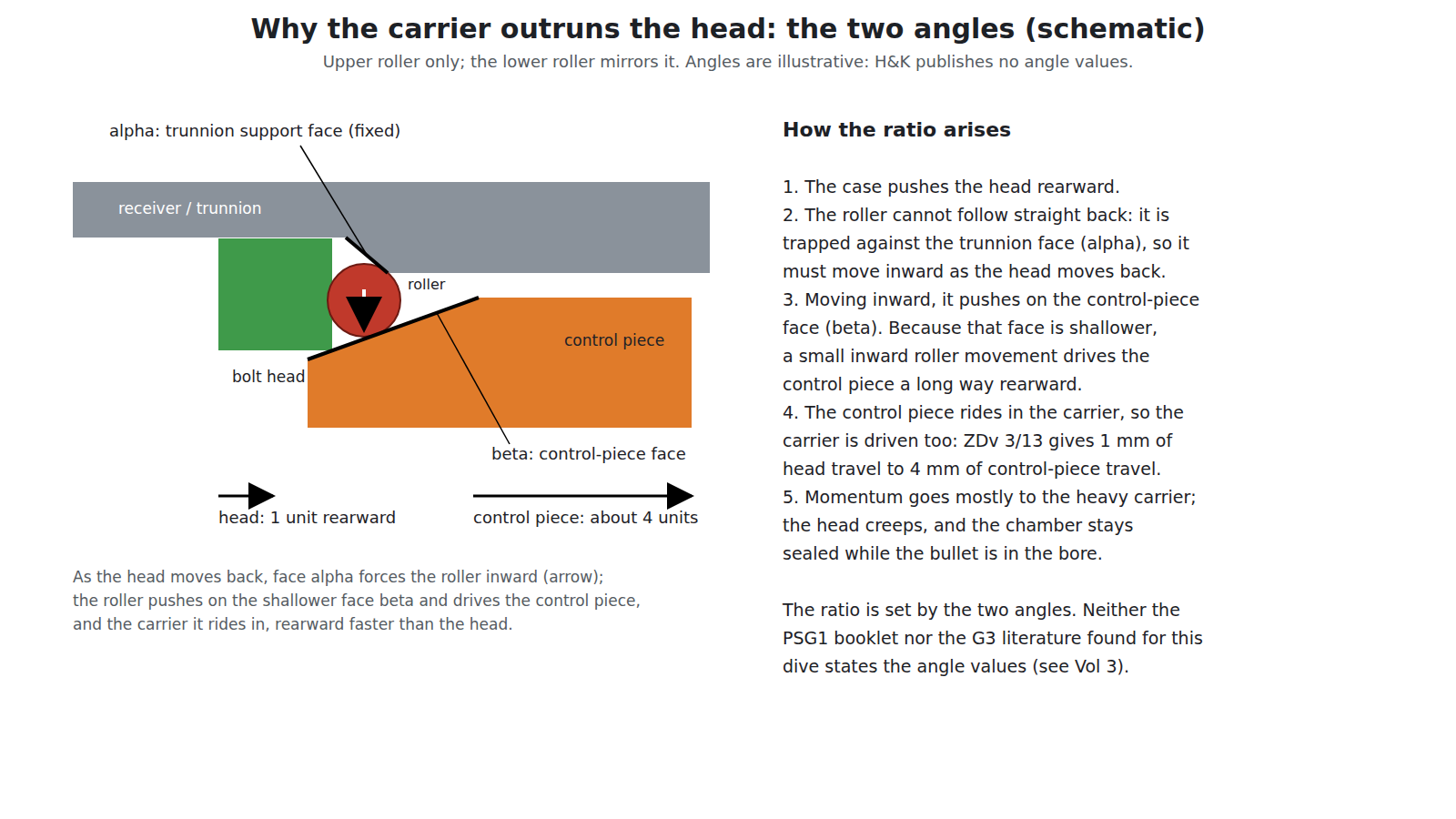
The booklet’s phrase is exact: the delay comes from “the matched angles of the control piece and the trunnion” (die abgestimmten Winkelverhältnisse von Steuer- und Verriegelungsstück).1 Two angled surfaces bear on each roller. The trunnion’s support face converts rearward movement of the head into inward movement of the roller; the control piece’s face converts inward movement of the roller into rearward movement of the control piece. The ratio between head travel and control-piece travel is set by the two angles together.
That is why the control piece is the part that tunes a roller-delayed gun, and why the trade sells them in different angles (Volume 9). The PSG1 booklet, the G3 description and the Bundeswehr regulation all give the principle and none gives an angle value. A secondary community reference gives the standard G3 control piece as 45 degrees and the PSG1’s and MSG90’s as 40 degrees, without citing a source; this dive repeats that figure only as unconfirmed, and it is not used anywhere as fact.5 No source found gives the trunnion’s angle.
3.8 The locking lever: why the bolt does not bounce
A bolt slamming into battery can rebound a fraction of a millimetre, and on a roller gun a rebound means the rollers are not fully out when the hammer falls. Every primary document found solves this the same way: a spring-loaded lever on the carrier drops into a notch in the bolt head as the bolt closes and holds the head against rebound.
- H&K’s G3 description: “The bolt head locking lever retains the bolt head by means of its shoulder at the moment the locking takes place, and a rebounding of the bolt is thus impossible.”4
- The Bundeswehr regulation: on closing, “the locking lever now enters the notch of the bolt head and so prevents it from rebounding.”2
- The PSG1 booklet lists the part in the bolt group: “bolt carrier with locking lever” (Verschlußträger mit Sperrhebel), and the bolt reassembly depends on it (Volume 4).1
The same idea is in an H&K patent filed in 1968 by Stanly Jauch and Herbert Meidel, for a “bipartite semirigid bolt” whose head and carrier are joined by a catch lever.6 A different solution, a “supplementary mass” of heavy-metal granules sealed in two bores of the bolt, is the subject of Theodor Koch’s 1966 patent.7 No primary source found says that any production G3 or PSG1 carrier contains such granules, and the documents that describe the production bolt name only the lever.
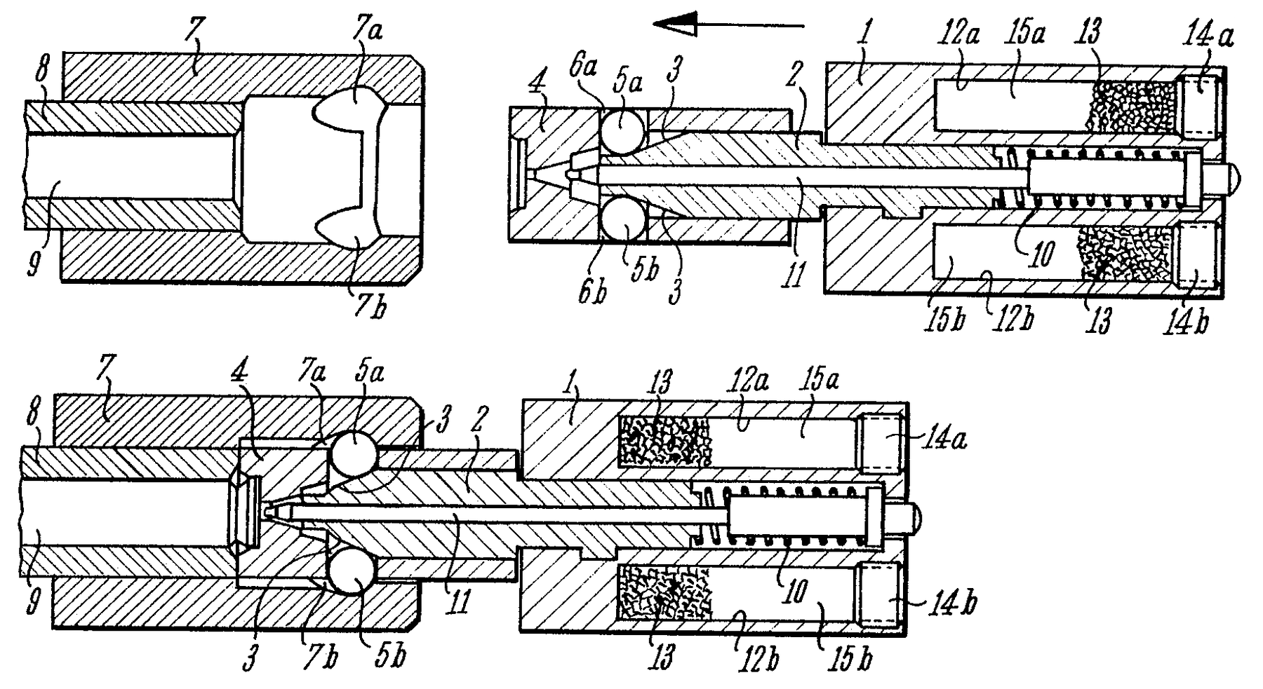
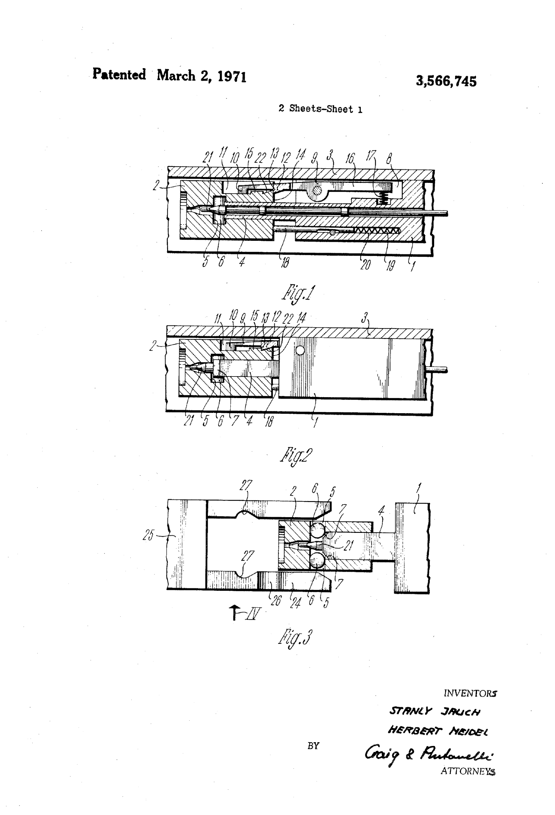
3.9 The fluted chamber
The other half of the solution is in the barrel. H&K’s G3 description: “The chamber has 12 flutes which facilitate the extraction of the cartridge case utilizing the gas pressure.” The Bundeswehr: “The chamber is provided with twelve relief grooves which, together with the gas pressure, ease the extraction of the case.”42
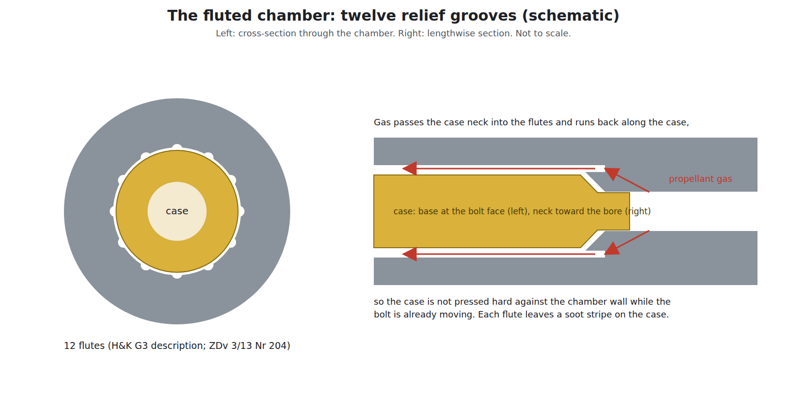
Gas escapes past the case neck into the flutes and runs back along the outside of the case body, so that the case is pressed outward by gas on the inside and inward by gas on the outside at the same time. It no longer grips the chamber wall, and the bolt can begin to move while pressure is still high without tearing the case apart. The flutes are cut in the chamber and stop short of the case head, which still seals at the rear.
H&K’s own patent for chamber grooves, Theodor Koch’s US 3,736,693 (German priority 1967), describes a chamber “provided with release grooves by virtue of polygonal shaping extending to a cylindrical sealing surface at the cap end of the cartridge”, formed by forging at the same time as the rifling.8 Whether the PSG1’s chamber is made that way is not established; the patent shows that H&K owned the method.
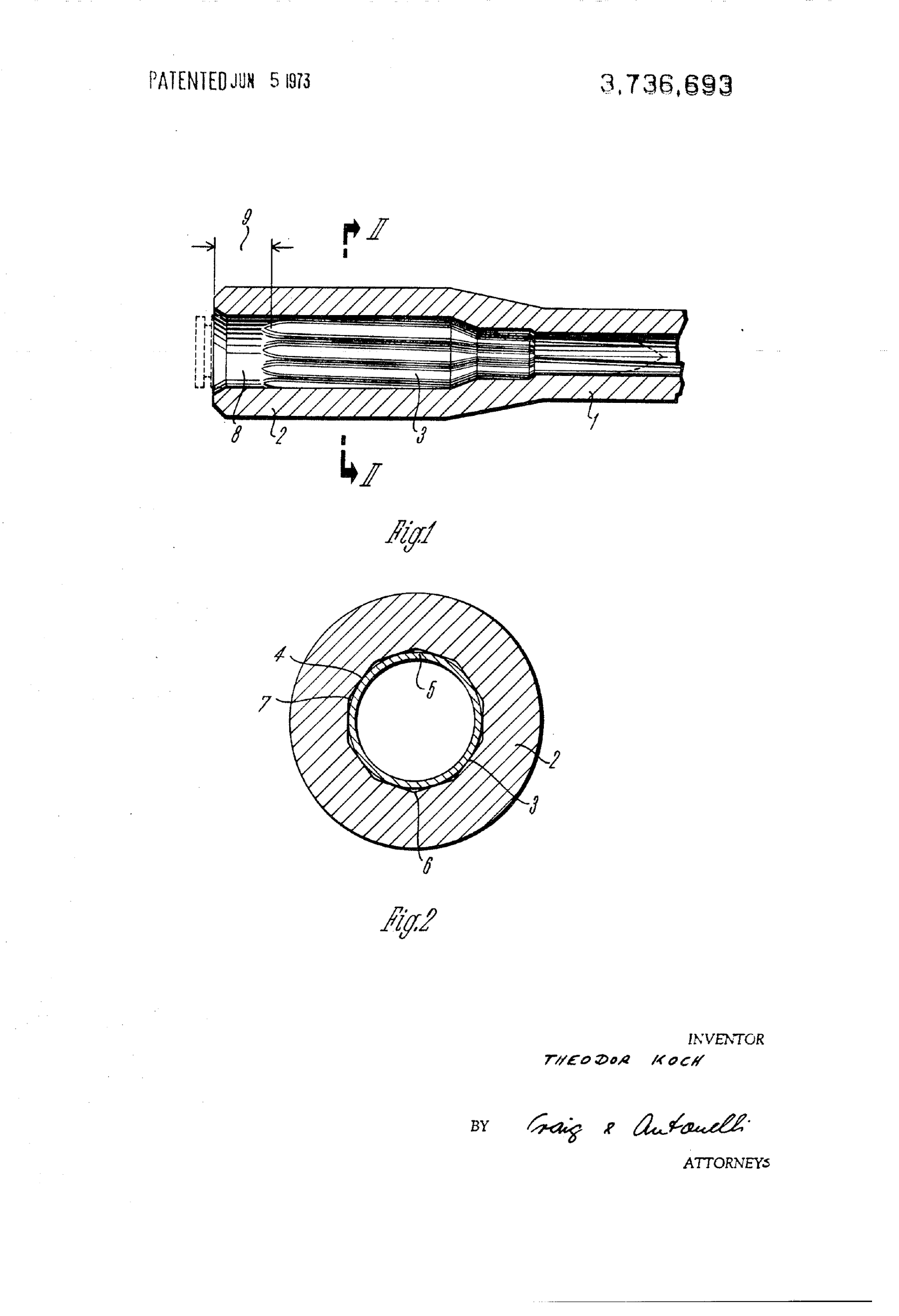
The PSG1’s chamber is fluted. H&K’s PSG1 booklet labels Entlastungsrillen in the chamber of its own sectional drawing.1 It does not state the number of flutes, and this dive does not assume that it is the G3’s twelve.
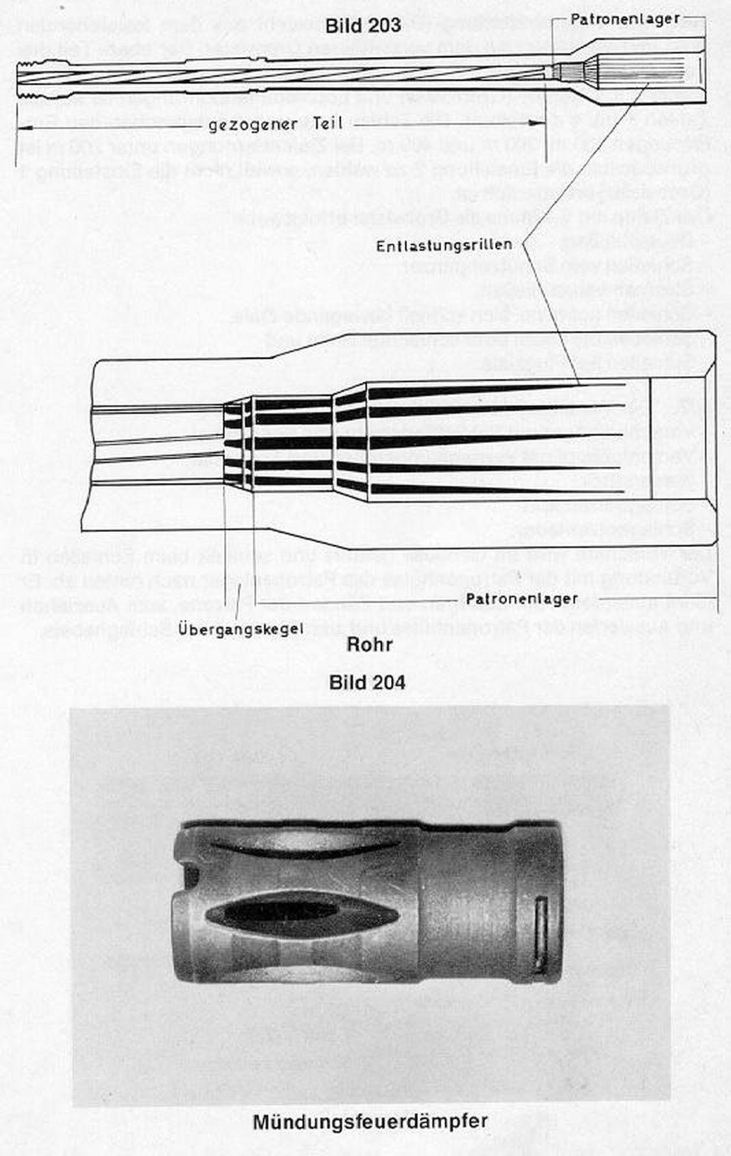
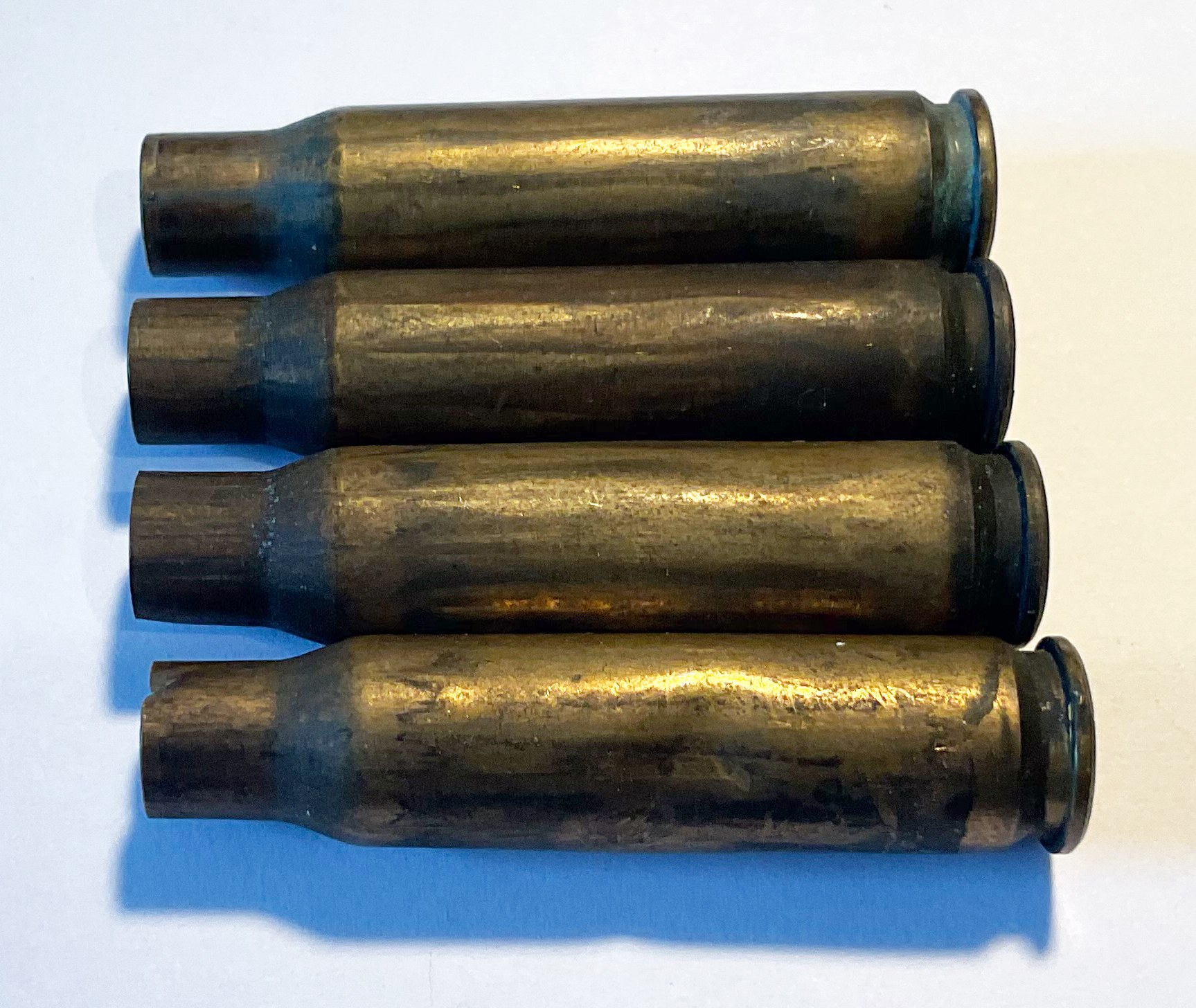
The flutes leave their mark on every fired case: a ring of soot stripes along the body, one stripe per flute. The Deutsches Waffen-Journal described the cases from a German PSG1 copy as having “a characteristic striped look; in addition they are slightly dented.”9 Volume 7 deals with what that means for a handloader.
3.10 The bolt gap
With the bolt locked, there is a small clearance between the front of the carrier and the rear of the bolt head. H&K’s G3 description lists it in its technical data as “Distance between bolt head and bolt head carrier: 0.5 – 0.1 mm”.4 The gap exists because the rollers are wedged out against the trunnion’s faces before the carrier reaches the head; its size depends on the rollers’ diameter, the trunnion recesses and the control piece, and so it is the measure of the locking geometry on a given rifle. As those surfaces wear the gap closes, and below the minimum the rollers are no longer held far enough out for the delay to work as designed. Measuring and correcting it with oversize rollers is armourer’s work (Volumes 4 and 9). No PSG1 bolt-gap figure was found.
3.11 The closing aid (Schließhilfe)
The PSG1’s most famous feature has the plainest name: Schließhilfe, “closing aid”. The booklet says it serves “for positive and low-noise closing of the bolt”, that it sits “behind the ejection port”, and how to use it:1
“Low-noise loading of the weapon. For low-noise loading do not let the cocking lever snap forward, but guide it slowly forward. To lock the bolt fully, push the closing aid forward.”
The reason it is needed follows from the cycle. A roller gun locks because the carrier, moving forward, drives the control piece between the rollers and wedges them out; the force to do that comes from the recoil spring and the carrier’s momentum. A bolt eased forward by hand arrives without momentum and can stop with the rollers not fully out and the locking lever not seated. The closing aid lets the shooter push it the last few millimetres. H&K’s word for what that achieves is “fully” (vollständig).
The booklet does not describe what is inside it. Secondary accounts compare it to the AR-15’s forward assist and say it engages serrations on the PSG1’s carrier; an American auction description of a PSG1 notes “the bolt carrier is properly serrated for the closure device”.1011 No patent for it was found. H&K Inc.’s 2007 MSG90 features list includes a “bolt closing aid for silent bolt closing”, so the MSG90 has one too.12
3.12 The trigger unit
The PSG1’s trigger is the change that most separates it from a G3 in the hand. The booklet: a Druckpunktabzug of “about 1.5 kp” weight, that is, a two-stage trigger with a defined second stage, its width adjustable by sliding the trigger shoe, which is clamped with an Allen key.1
H&K’s figures for the pull disagree (Volume 2): about 1.5 kp in the booklet, “about 12–15 N” on H&K Germany’s 2012 page (the same thing, about 2.7 to 3.4 lb), and “Aprox. 30-55 N” on H&K Inc.’s 2007 page, which is a service-trigger figure and probably an error. H&K’s 2008 catalogue says “crisp three pound trigger pull and adjustable trigger shoe on PSG1A1 & MSG90A1”, so H&K itself gives the MSG90A1 the same pull and shoe.13 Reviewers who have shot PSG1s describe it the same way: Forgotten Weapons calls it “an excellent 3lb crisp trigger” that “replaced the standard heavy and mushy G3 trigger”; Sniper Central’s test rifle was “set at 3 lbs”.1415
The trigger is a self-contained box (Abzugkasten) that sits in the grip, held by the safety lever acting as a cross pin, with a safety of two positions, 0 and 1.1 The user may not dismantle the box (Volume 4). Its internal layout is not published in any document found. The Firearm Blog says it “breaks at about 3 pounds, but has a second hammer spring” that engages partway through the hammer’s travel to shorten lock time; that statement is unconfirmed and is given only as reported.16
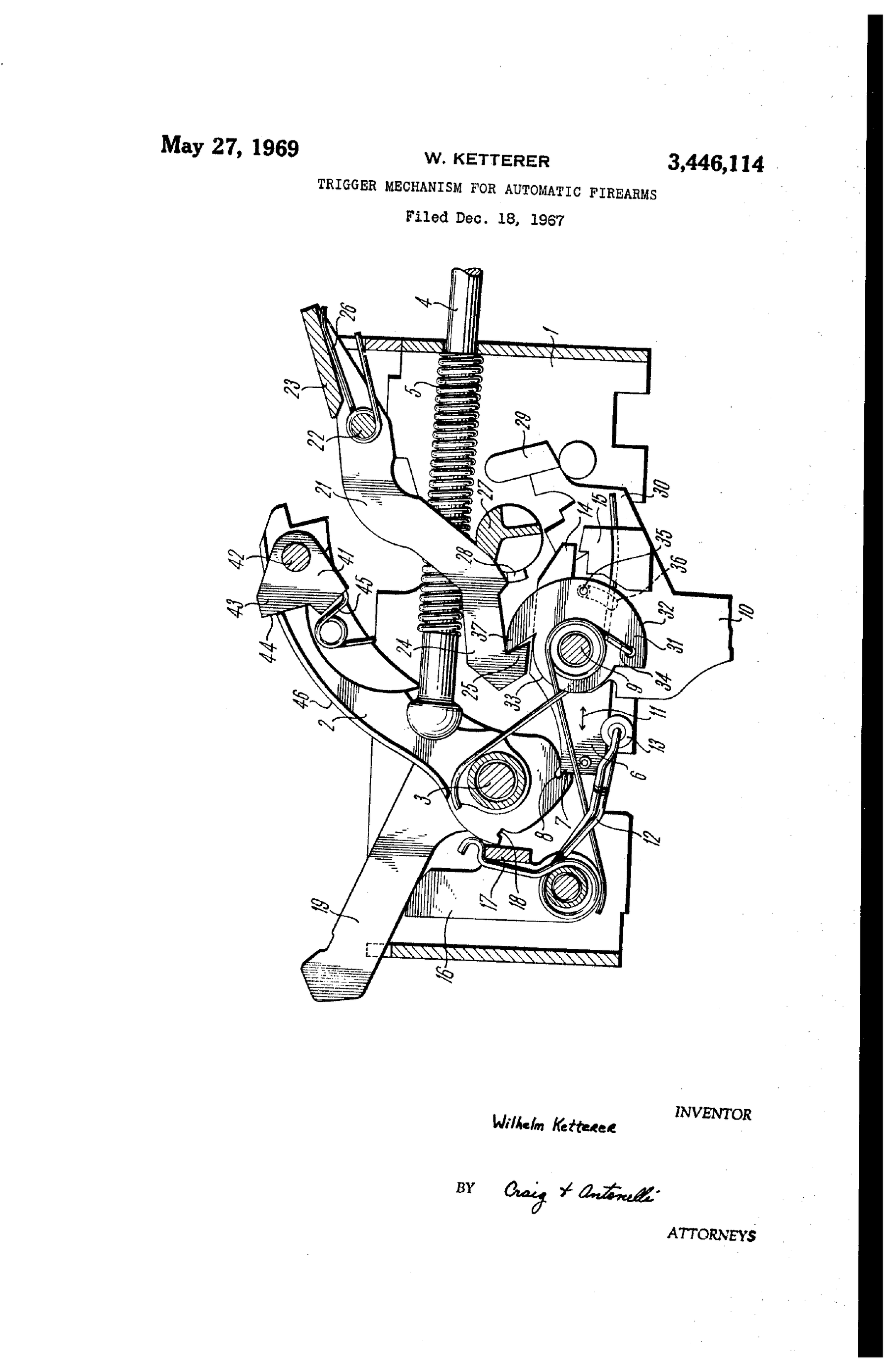
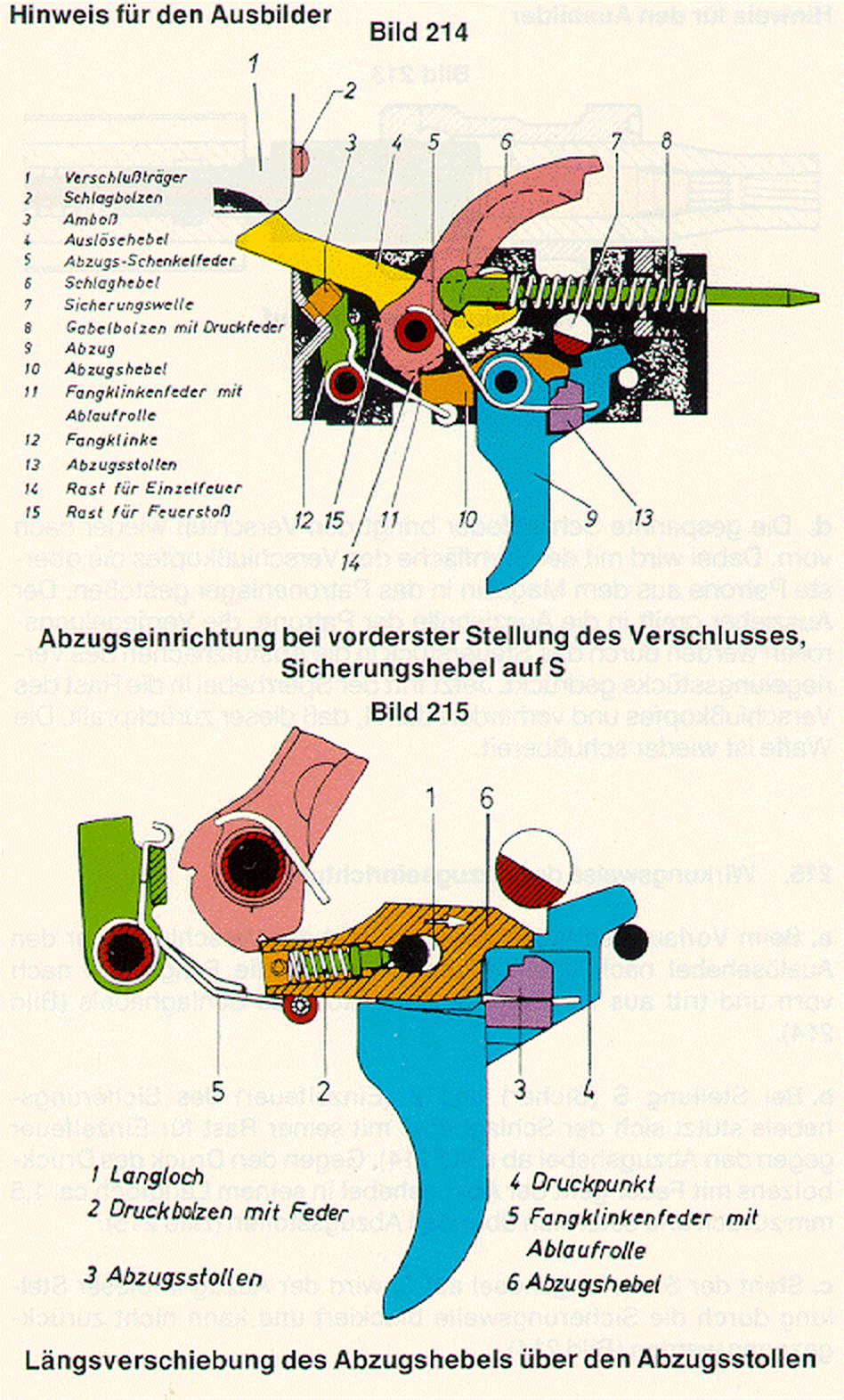
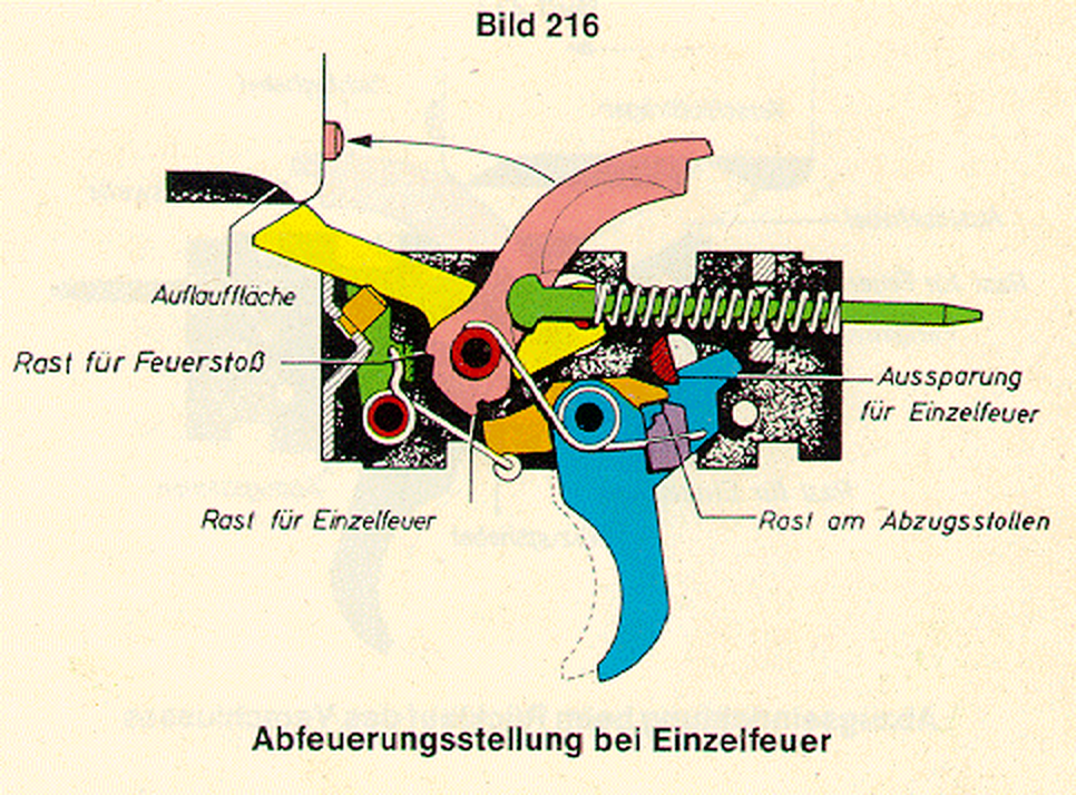
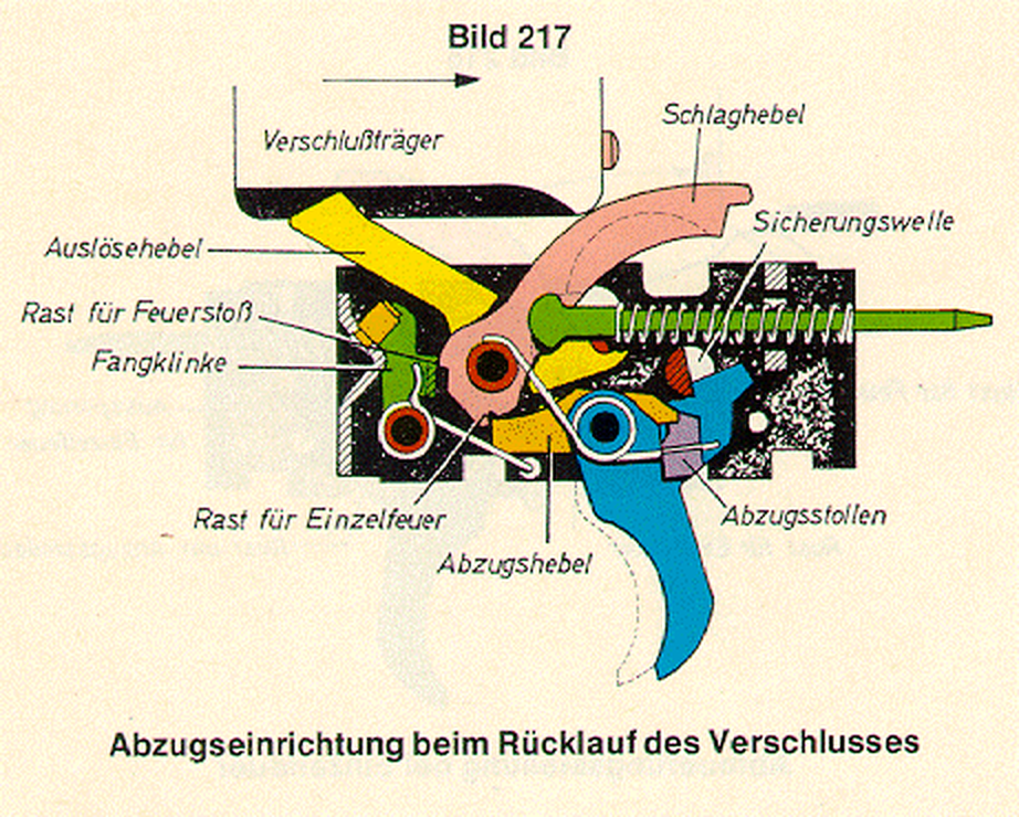
For comparison, the G3’s service trigger is drawn in full in the Bundeswehr regulation. Its trigger lever can shift about 1.5 mm in its slotted hole, which is how the single-fire disconnection works; on single fire, the hammer is held at the single-fire notch and released when the trigger is pulled.2 The PSG1’s box is a different mechanism and the G3 drawings are shown only as the family’s published reference. So is the one H&K trigger patent of the period found for this dive: Wilhelm Ketterer’s US 3,446,114 of 1969, a select-fire trigger for H&K’s automatic weapons with a catch lever that holds the bolt open on automatic. It is not a PSG1 trigger and is shown only as an example of H&K trigger design of the 1960s.17
3.13 Barrel, receiver and mount
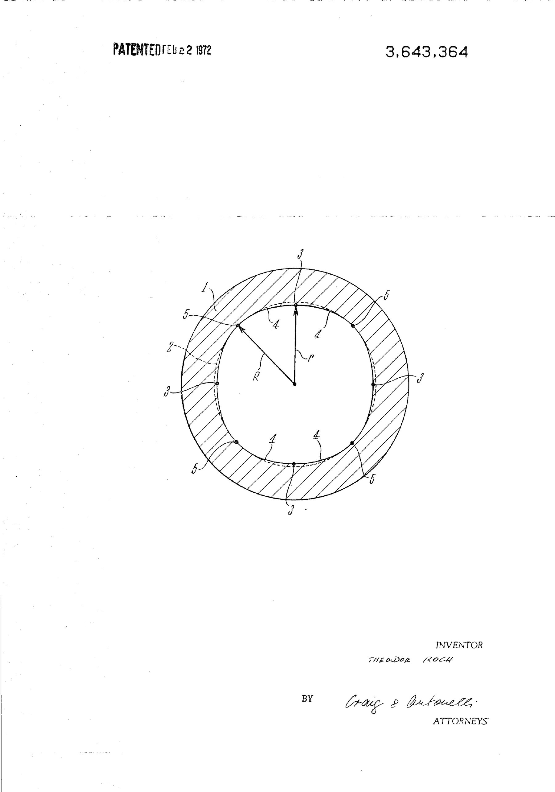
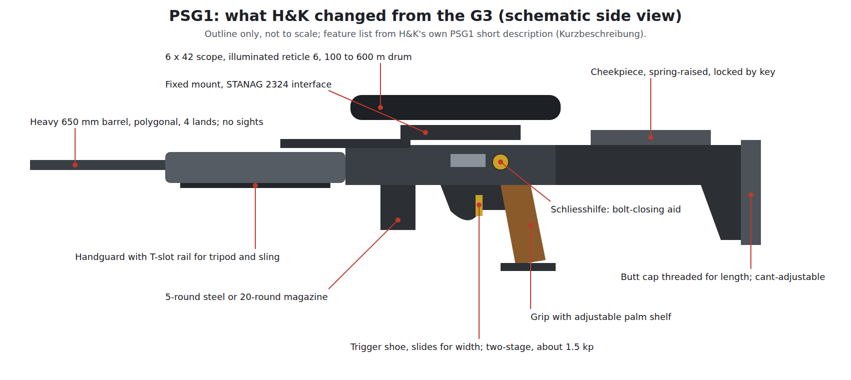
Barrel. 650 mm, polygonal, four “lands”, right-hand, pressed into the trunnion and pinned (booklet); “26 inch heavy polygonal bore hammer forged barrel”, “internally hard chrome plated” (H&K Inc., 2007); “free-floating and cold-hammer forged for accuracy and long life (15,000 rounds)” (H&K catalogue, 2008).11813 H&K’s polygon rifling is the subject of Theodor Koch’s US 3,643,364: a bore whose cross-section is “a regular polygon with rounded sides and corners”.19 The twist rate is not given in the PSG1 booklet. The G3’s is 305 mm (12 in), right-hand.4 The PSG1’s twist is often given as the same, but no H&K document read says so. An American auction house described PSG1 barrels as “stainless steel”; H&K’s own description of an internally chromed, hammer-forged barrel is preferred here.11
The barrel is free of the handguard. On the G3 the handguard hangs from the cocking tube, not the barrel, and H&K’s G3 description calls the G3A4’s arrangement a “free floating barrel”; the PSG1’s heavier barrel sits in the same way.410
Receiver. The PSG1 receiver is the G3’s stamped steel box stiffened by reinforcing strips welded along its sides. H&K’s documents do not mention them; the secondary sources agree on them: Forgotten Weapons (“stiffening bars welded to the sides of the receiver”), The Firearm Blog (“large, steel reinforcement rails located on the sides”), and the Deutsches Waffen-Journal, which describes the same welded strips on the German copy “as on the historical original” and notes that a retractable stock could no longer be fitted.14169
Mount. The booklet’s “telescope mount fixed to the weapon, with interface dimensions to STANAG 2324” replaces the G3’s clamp-on claw mount. Sniper Central describes the PSG1 scope mount as attaching “with two hex screws to welded-on scope bases”; Forgotten Weapons, “proprietary mounting points welded to the receiver”.11514 Volume 6 covers the optics.
3.14 Stock, recoil spring and buffer
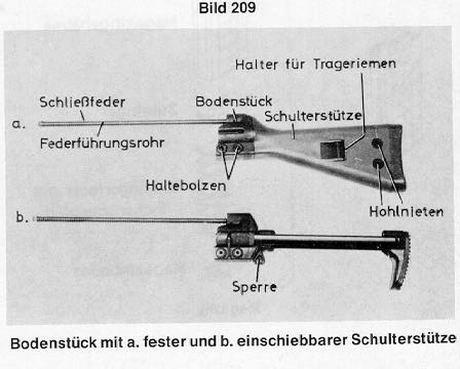
The PSG1 stock is fixed to the receiver in the G3 manner, by an end cap held with two retaining pins, and the end cap carries the recoil-spring guide tube with its spring and the buffer.1 The adjustments are the PSG1’s own: a spring-loaded cheekpiece that rises to its highest position when unlocked and is pushed down to the shooter’s height and locked with a key; a butt cap threaded onto the stock, turned to set the length of pull and clamped; and a butt plate adjustable for angle.1 H&K Germany’s 2012 data gives the PSG1 A1’s length as 1,223 to 1,260 mm, a range of 37 mm that is the length-of-pull adjustment.20
3.15 Feeding and ejection
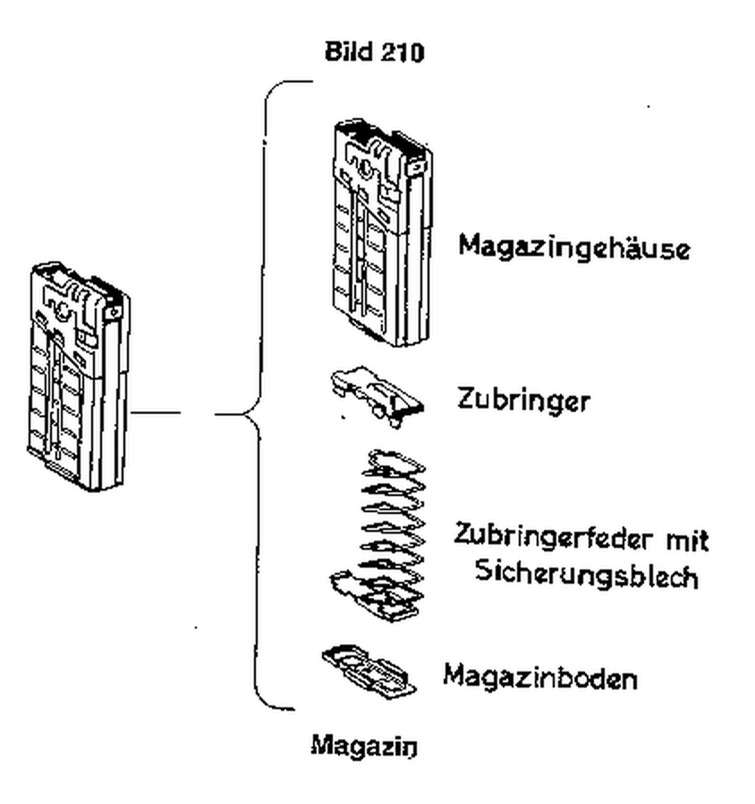
The PSG1 takes G3 magazines: steel 5-round magazines as standard and 20-round magazines as an option (booklet).1 Cases are “ejected to the right” (H&K Inc.).18 The roller gun ejects hard. Sniper Central reported “mangled brass ejected 30+ feet from the rifle” from a PSG1, and wrote that it throws cases about 10 metres, which can give away a position and makes brass hard to recover.1521 The German copy tested in 2023 has a welded case deflector to throw cases away from the shooter, which, the magazine noted, the standard G3 lacks; on that rifle it took the place of the closing aid.9
3.16 What the PSG1 changes from the G3, and how sure each claim is
Table 3 — What the PSG1 changes from the G3, and how sure each claim is
| Change | Source | Confidence |
|---|---|---|
| Heavy 650 mm polygonal barrel, internally chromed, hammer forged | H&K booklet; H&K Inc. 2007 | Primary |
| No iron sights; fixed mount to STANAG 2324; 6×42 telescope (A1: Schmidt & Bender) | H&K booklet; H&K Inc. 2007 | Primary |
| Closing aid behind the ejection port | H&K booklet | Primary |
| Two-stage trigger of about 1.5 kp with adjustable shoe; safety 0/1 | H&K booklet | Primary |
| Grip with adjustable palm shelf; stock adjustable for length, comb and cant | H&K booklet | Primary |
| Handguard with T-slot for tripod and sling | H&K booklet | Primary |
| Fluted chamber (count not stated) | H&K booklet drawing | Primary |
| Receiver stiffened by welded side reinforcement | Forgotten Weapons; The Firearm Blog; DWJ | Consistent secondary |
| Carrier serrated for the closing aid; PSG1-marked bolt head | Auction description; forum reports | Secondary |
| Redesigned extractor and rollers | Forgotten Weapons (“the extractor and locking rollers were redesigned”) | Secondary |
| Rollers “with flats”, “semi-cylindrical”, or “crescent shaped titanium” | Modern Firearms; English Wikipedia; The Firearm Blog respectively | Secondary and mutually inconsistent |
| Control piece of 40 degrees against the G3’s 45 | Community wiki, uncited | Unconfirmed |
| Second hammer spring for shorter lock time | The Firearm Blog | Unconfirmed |
The roller claims deserve a remark. Three secondary sources describe the PSG1’s rollers three different ways, and none cites a document; the booklet’s drawings, at the resolution of the scan read, do not show the rollers’ shape clearly enough to decide. A dealer’s catalogue does list the PSG1 and MSG90 bolt head as a separate part from the G3’s, at a price several times higher, which supports the general claim that the bolt head is different without settling how.22
3.17 What could not be established
- The PSG1’s twist rate, flute count, control-piece angle and roller shape from any H&K document.
- The internal mechanism of the PSG1 trigger box and of the closing aid.
- The trunnion angle, bolt and carrier masses and recoil-spring rate, for any H&K roller rifle.
- Whether the H&K patents shown describe production parts.
- A PSG1 bolt-gap figure.
References
Footnotes
-
Heckler & Koch GmbH, Kurzbeschreibung des Präzisionsschützengewehres PSG 1 (Oberndorf, n.d.), printed pp. 2–16, 26–35, 45. Internet Archive collection “MManuals”, https://archive.org/download/MManuals/HkPsg1.pdf, consulted 2026-10-18. H&K copyright; quoted in translation. ↩ ↩2 ↩3 ↩4 ↩5 ↩6 ↩7 ↩8 ↩9 ↩10 ↩11 ↩12 ↩13 ↩14 ↩15
-
Bundesministerium der Verteidigung, ZDv 3/13 Das Gewehr G3 (Bonn, 13 December 1978; amendment no. 38 of 8 January 1999), Nr 204, 214–215; Bild 202–203, 209–210, 212–213, 216–217. Wikimedia Commons, https://commons.wikimedia.org/wiki/File:ZDv_3-13_Das_Gewehr_G3_(1999).pdf, public domain per Commons, consulted 2026-10-18. Translated for this dive. ↩ ↩2 ↩3 ↩4 ↩5 ↩6 ↩7 ↩8 ↩9 ↩10
-
Edward Stecke, US Patent 2,089,671, “Automatic Firearm”, issued 10 August 1937, p. 1. https://patents.google.com/patent/US2089671A, consulted 2026-10-18. ↩
-
Heckler & Koch, Technical Description of the Automatic Rifle HK G3, Cal. 7.62 mm NATO (English; licensed reprint, copyright Heckler & Koch Inc.), printed pp. 5, 9, 12–13, 27–28. Internet Archive collection “MManuals”, https://archive.org/download/MManuals/HkG3AutomaticRifleCal7.62mmNato.pdf, consulted 2026-10-18. ↩ ↩2 ↩3 ↩4 ↩5 ↩6 ↩7 ↩8
-
“HK Bolt Gap” and locking-piece table, Thinline Weapons wiki, https://thinlineweapons.com/wiki/index.php/HK_Bolt_Gap, edited 21 February 2026, consulted 2026-10-18. No sources cited by the wiki. ↩
-
Stanly Jauch and Herbert Meidel, assignors to Heckler & Koch GmbH, US Patent 3,566,745, “Automatic Firearm Bipartite Semirigid Bolt”, issued 2 March 1971. https://patents.google.com/patent/US3566745A, consulted 2026-10-18. ↩
-
Theodor Koch, assignor to Heckler & Koch GmbH, US Patent 3,283,435, “Breech Closure”, issued 8 November 1966. https://patents.google.com/patent/US3283435A, consulted 2026-10-18. ↩
-
Theodor Koch, assignor to Heckler & Koch GmbH, US Patent 3,736,693, “Firearm Barrel”, issued 5 June 1973. https://patents.google.com/patent/US3736693A, consulted 2026-10-18. ↩
-
Franz Keck, “Präzision mit Geschichte”, Deutsches Waffen-Journal, January 2023, pp. 20–25. https://www.schwabenarmsgmbh.de/index_htm_files/Testbericht%20DWJ%20Ausgabe%2001-2023%20SAR%20M41%20PSG.pdf, consulted 2026-10-18. Translated for this dive. ↩ ↩2 ↩3
-
Maxim Popenker, “Heckler – Koch PSG1 sniper rifle (Germany)”, Modern Firearms, undated, https://modernfirearms.net/?p=7379, consulted 2026-10-18. ↩ ↩2
-
Rock Island Auction Company, 25 August 2024, lot 3589, https://www.rockislandauction.com/detail/4092/3589/heckler-koch-psg1-semiautomatic-sniper-rifle-with-scope, consulted 2026-10-18. ↩ ↩2
-
Heckler & Koch Inc., MSG90 A1 features page, hk-usa.com, Wayback capture of 22 March 2007, http://web.archive.org/web/20070322080929/http://www.hk-usa.com:80/le_msg90_features.html, consulted 2026-10-18. ↩
-
Heckler & Koch (Ashburn, Virginia), Military & Law Enforcement catalogue, ”© HKDCS 01.12.08”, “HK Precision Rifles”, catalogue p. 19, http://photos.imageevent.com/smglee/cltactical/HK%20Military%20LE%20Catalog.pdf, consulted 2026-10-18. ↩ ↩2
-
Ian McCollum, “The Ultimate German Sniper Rifle: the H&K PSG-1 at James D Julia”, Forgotten Weapons, 18 March 2017, https://www.forgottenweapons.com/the-ultimate-german-sniper-rifle-the-hk-psg-1-at-james-d-julia/, consulted 2026-10-18. ↩ ↩2 ↩3
-
Melvin Ewing, “H&K PSG-1 Full Review”, Sniper Central, 26 August 2020, https://snipercentral.com/hk-psg-1-full-review/, consulted 2026-10-18. ↩ ↩2 ↩3
-
Alex C., “H&K PSG1 Sniper Rifle Overview”, The Firearm Blog, 18 February 2016, https://www.thefirearmblog.com/blog/2016/02/18/hk-psg1-sniper-rifle-overview/, consulted 2026-10-18. ↩ ↩2
-
Wilhelm Ketterer, assignor to Heckler & Koch GmbH, US Patent 3,446,114, “Trigger Mechanism for Automatic Firearms”, filed 18 December 1967, issued 27 May 1969. https://patents.google.com/patent/US3446114A, consulted 2026-10-18. ↩
-
Heckler & Koch Inc., PSG1 A1 features and general pages, hk-usa.com, Wayback captures of 28 and 20 March 2007, http://web.archive.org/web/20070328065452/http://www.hk-usa.com:80/le_psg1_features.html and http://web.archive.org/web/20070320220441/http://www.hk-usa.com:80/le_psg1_general.html, consulted 2026-10-18. ↩ ↩2
-
Theodor Koch, US Patent 3,643,364, “Rifled Gun Barrel with the Interior Cross-Sectional Configuration Defining a Regular Curvilinear Polygon”, issued 22 February 1972. https://patents.google.com/patent/US3643364A, consulted 2026-10-18. ↩
-
Heckler & Koch GmbH, “PSG1 A1” technical data, Wayback capture of 18 August 2012, http://web.archive.org/web/20120818005626/http://www.heckler-koch.com:80/en/military/products/precision-rifles/psg1-a1/psg1-a1/technical-data.html, consulted 2026-10-18. ↩
-
Melvin Ewing, “HK PSG-1”, Sniper Central, 26 August 2020, https://snipercentral.com/hk-psg-1/, consulted 2026-10-18. ↩
-
Midwest Gun Works, “PSG1/MSG90 Complete Bolthead”, code 225656, $598.00, sold out, https://www.midwestgunworks.com/page/mgwi/prod/225656, consulted 2026-10-18 (as recorded in this dive’s research notes). ↩
Comments (0)