Wireless Power Only · Volume 3
Two Sources, One Gun — Logic Power, Back-Feeding and Ground
Which source powers the Pico and why, what the USB specification forbids a battery-powered device to do, what the stock RP2040 driver does anyway, ideal-diode ORing with part numbers, a rail that switches on with the cable, and where the pulse current goes
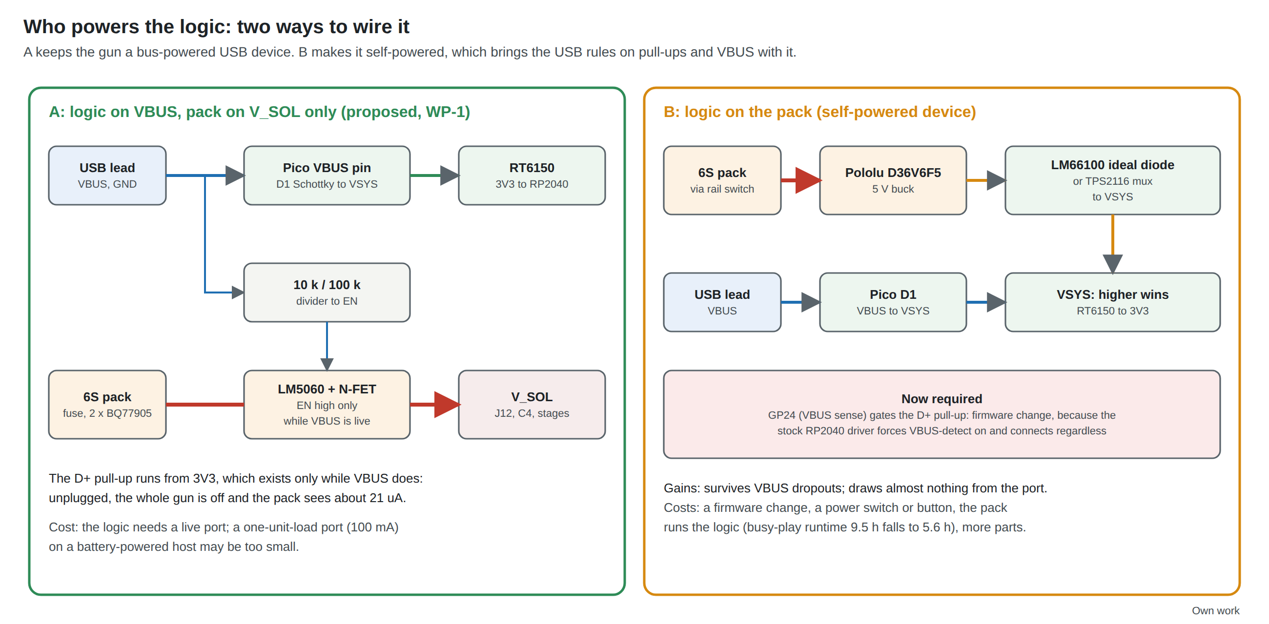
The wired gun has one source of each kind: the PC’s port for the logic and a brick for the coils. A battery gun with a USB lead has two sources that can reach the same nets, the PC’s VBUS and the pack, and every place they could meet is a place where one can feed the other. This volume decides which source powers what, shows what goes wrong when the choice is made carelessly, and follows the pulse current to see what the new ground arrangement buys.
3.1 The Rules a Battery Gun Must Keep
The USB 2.0 specification is short and absolute about a device that has its own power. Section 7.2.1:1
“No device shall supply (source) current on VBUS at its upstream facing port at any time. From VBUS on its upstream facing port, a device may only draw (sink) current. They may not provide power to the pull-up resistor on D+/D- unless VBUS is present (see Section 7.1.5). When VBUS is removed, the device must remove power from the D+/D- pull-up resistor within 10 seconds.”
And section 7.1.5.1, on the 1.5 kΩ pull-up a full-speed device puts on D+ to announce itself:
“The voltage source on the pull-up resistor must be derived from or controlled by the power supplied on the USB cable such that when VBUS is removed, the pull-up resistor does not supply current on the data line to which it is attached.”
A bus-powered device keeps both rules without trying: when VBUS goes, everything goes. A self-powered device, one whose function runs from its own supply, must arrange it. The specification describes such a device in section 7.2.1.5, with the function controller powered “either from the upstream bus via a low-power regulator or from the local power supply”, and allows it to draw up to one unit load from VBUS for its USB interface.1
The whole of this volume follows from one question: is the gun bus-powered or self-powered?
3.2 Option A: Logic on VBUS
The proposal (WP-1): the logic runs from VBUS, and the pack feeds only V_SOL. The gun stays a bus-powered device, as the wired gun is:
- Both USB rules are kept by construction. The D+ pull-up is powered from the Pico’s 3.3 V, which exists only while VBUS does. No gun-side source is connected to VBUS at all.
- No firmware change. The stock RP2040 driver’s behaviour (Section 3.3) is harmless when the chip has no power without VBUS.
- The pack’s job is simple. It feeds three DRV8251A stages through one switch, and nothing else.
- The pack is not drained by the logic. At 0.5 W through a regulator, the logic is the largest steady load a pack would otherwise carry (LiPo Batteries Vol 3). Taking it off the pack nearly doubles busy-play runtime (Volume 4).
Its costs are two. The gun needs a live port to work at all, which it needs anyway to send data. And the port must supply the logic’s 100 to 150 mA (Power Supplies Vol 1). Every desktop port does: USB 2.0 requires “systems that obtain operating power externally” to supply five unit loads, 500 mA, to each port. But it allows “battery-powered systems” to supply “either one or five unit loads” (section 7.2.1),1 and one unit load is 100 mA. A handheld PC or a battery-powered single-board computer with low-power ports could leave the gun short. That is the one case where Option B earns its complexity; the platform question belongs to Mobile and Handhelds.
3.3 Option B: Logic on the Pack, and What the RP2040 Driver Does
Option B powers the Pico from the pack through a small buck regulator, the Pololu D36V6F5 already sized in LiPo Batteries Vol 3, section 3.7, entering at VSYS through an ideal diode (Section 3.4). It is the arrangement the fully wireless gun must use. Doing it in a gun that also has a USB lead makes the gun a self-powered device, and the RP2040’s USB driver then matters.
What the stock driver does. OpenFIRE builds on TeamOpenFIRE’s patched Arduino-Pico core, 4.5.4-tusb, with Adafruit’s TinyUSB library (Our Firmware Vol 4). The RP2040 device driver in TinyUSB, dcd_rp2040.c, carried identically on the master branches of both TinyUSB and Adafruit’s Arduino port, contains this:2
”// Current implementation force vbus detection as always present, causing device think it is always plugged into host. // Therefore, it cannot detect disconnect event, mistaken it as suspend. // Note: won’t work if change to 0 (for now)”
#define FORCE_VBUS_DETECT 1
In dcd_init() the driver sets the controller’s VBUS-detect override (“Force VBUS detect so the device thinks it is plugged into a host”) and then calls dcd_connect(), which is “connect by enabling internal pull-up resistor on D+/D-”.2
On a Pico powered only by VBUS that is irrelevant. On a Pico powered from a pack it means the D+ pull-up is switched on at boot whether or not a host is there, and stays on when the lead is unplugged. Plugged into a PC that is switched off, the gun drives 3.3 V through 1.5 kΩ into the PC’s 15 kΩ pull-down and its transceiver’s protection diodes, a current of up to about 2 mA into a powered-down port. It is exactly what section 7.2.1 forbids. It will rarely damage anything, but it can hold a host’s port in a half-powered state, and a kit that does it fails the rule that D11 makes binding.
Option B therefore needs:
- A VBUS sense the firmware reads. The Pico already has one: GPIO24 is “VBUS sense - high if VBUS is present, else low”, with resistors that pull VBUS to 0 V when nothing is connected.3
- A driver change in the fork so that the pull-up follows GPIO24: disconnect (TinyUSB’s
tud_disconnect()) within 10 seconds of VBUS going away, connect only when it returns. The comment above says the driver’s own VBUS-detect path “won’t work if change to 0 (for now)”, so the change is a fork task, not a configuration switch (Our Firmware). The master branches were read; the copy in the pinned 2025 core (FW-3) was not checked line by line. - A way to turn the pack’s logic supply off. A self-powered gun on a shelf runs its logic from the pack until something switches it off; at about 0.5 W through the buck, a 450 mAh pack is flat in well under a day (Volume 4). A power switch, a soft-latch button, or a timeout in firmware is needed. Option A gets this free (Section 3.5).
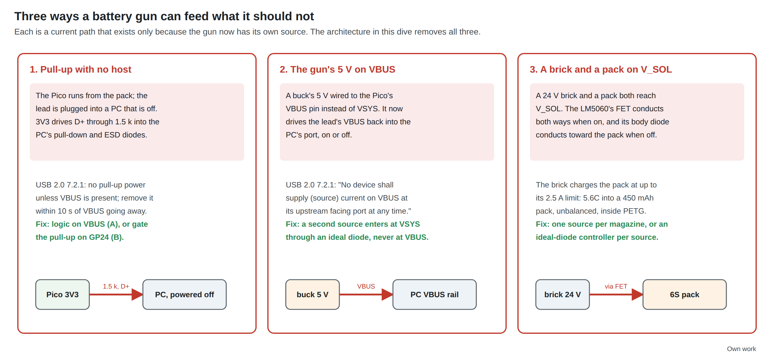
The second trap is wiring. A 5 V source must never be connected to the Pico’s VBUS pin. VBUS on the Pico is the USB connector’s VBUS, joined to the lead; anything driven onto it is driven up the lead into the host, the first sentence of section 7.2.1. The Pico datasheet’s own guidance is to feed a second source into VSYS, through a diode or a P-channel MOSFET, “with the diodes preventing either supply from back-powering the other”.3 The same point applies to the reference board’s NeoPixel and VBUS-rumble outputs: they hang off VBUS as loads, which is allowed; nothing on the gun may source into it.
3.4 ORing Parts, If the Logic Ever Has Two Sources
Option A needs none of these. They are here for Option B, for the fully wireless gun (which keeps USB for configuration), and for the Stage 2 board, which will have no Pico module and so no on-board D1.
Table 1 — 3.4 ORing Parts, If the Logic Ever Has Two Sources
| Part | What it is | Key figures (maker’s data sheet) | Why or why not |
|---|---|---|---|
| Schottky diode into VSYS | The Pico datasheet’s “simplest way” | One diode drop on the second source | Works; loses about 0.3 V and splits the load with VBUS unpredictably when the two are close |
| Diodes DMG2305UX P-FET, gate on VBUS | The Pico datasheet’s “improved way”: the FET “will disconnect the secondary source when VBUS is present" | "maximum Vt of 0.9 V and Ron of 100 mΩ (at 2.5 V Vgs)“3 | Good when VBUS should win; wrong for the low-power-port case, where the pack should win |
| TI LM66100 | Single ideal diode with a comparator enable; two make an OR | 1.5 to 5.5 V, 1.5 A, 79 mΩ at 5 V, 150 nA quiescent, SC-70-64 | Proposed for Option B: one LM66100 from the buck to VSYS, the Pico’s own D1 for VBUS. The buck’s 5.0 V through 79 mΩ sits above VBUS less D1’s drop, so the pack carries the load and the port is nearly unloaded |
| TI TPS2116 | Two-input power mux with priority mode | 1.6 to 5.5 V, 2.5 A, 40 mΩ, 1.32 µA quiescent; priority mode keeps VIN1 while PR1 is above 0.92 to 1.08 V; reverse-current blocking; ST pin low when VIN1 is not in use; SOT-5835 | Proposed for the Stage 2 board, which has no D1: VIN1 from the buck (priority), VIN2 from VBUS, and ST to a GPIO if one is free |
Prices for the TI parts were not shown on TI’s pages when read; they are priced at order time. The DMG2305UX’s price was not checked.
3.5 A Rail That Switches On With the Cable
The LiPo dive puts an LM5060 high-side controller and a 60 V N-channel MOSFET between the protected pack and V_SOL, for soft start, under- and over-voltage lockout and a fault latch (LB-4, LiPo Batteries Vol 4). It leaves open what drives its enable. In this architecture the answer is VBUS (proposed row WP-2).
The LM5060’s EN pin reads high above 2.00 V and low below 0.80 V, has a 6 µA internal pull-down “to ensure the EN pin is low in an open circuit condition”, and is rated to 75 V. With EN low the part enters “a low current (disabled) state”, drawing 9 µA typical and 15 µA maximum from its VIN pin; enabled, it draws 1.4 mA typical.6 VBUS at 4.75 to 5.25 V clears the 2.00 V threshold with room for a series resistor:
- EN = VBUS through 10 kΩ, with 100 kΩ from EN to ground so that a lead plugged into an unpowered port, or VBUS decaying through the Pico’s pull-down, reads low promptly. The 10 kΩ limits any current from a VBUS transient into the pin. The values are a starting point to check on the bench, not a calculation the data sheet requires.
What it buys:
- The gun turns itself off. Unplug the lead and the rail goes. The pack then sees only the LM5060’s disabled current and the two BQ77905s: about 21 µA, against about 100 mW with the rail left on (Volume 4). A gun left plugged into nothing for a month loses a few percent of its charge rather than going flat in three days.
- No power switch. There is nothing for a player to forget.
- A latched fault clears with a re-plug. The LM5060 holds a fault “latched off until either the enable input or the UVLO input is toggled low and then high”.6 Pulling and replacing the lead is that toggle, which is the natural thing a player does when a gun stops kicking.
- The coils cannot fire before the logic is alive. V_SOL exists only after VBUS, so the Pico is powered before the stages can see a rail. The DRV8251A inputs are held low through boot by the board’s 4.7 kΩ pull-downs (Reference Electronics Vol 8).
What it does not do: it cannot tell the firmware that the rail is up. The LM5060’s power-good output (nPGD) would need a GPIO, and the kit-camera carrier has no spare (FW-6). If the pack is flat or the protector has opened, the gun simply aims without kicking. That is a graceful failure; a firmware warning would need a pin.
3.6 The Two-Source Hazard on V_SOL
A tempting design is a gun that takes either source on V_SOL: the brick when one is to hand, the pack when not, or both. It needs more care than it looks.
The LM5060 drives a single N-channel MOSFET with its source toward the load. When the switch is on, the MOSFET conducts in both directions. When it is off, its body diode conducts from V_SOL toward the pack. So if a 24 V brick is on V_SOL and the pack is below 24 V, the brick charges the pack whether the switch is on or off: through the channel at whatever current the brick will give, or through the body diode less a diode drop. The GST60A24 class brick’s limit is 2.5 A, which is 5.6C into a 450 mAh pack, with no balancing and no charge termination, in a printed shell. The LiPo dive’s charging rule exists to prevent exactly this (LiPo Batteries Vol 5). The pack protector’s charge FET would eventually open on a cell over-voltage, but it is a last line, not a charger.
Three ways to deal with it:
Table 2 — Three ways to deal with it
| Approach | How | For | Against |
|---|---|---|---|
| One source per magazine (proposed, WP-3) | The battery magazine has no brick input and no GX; the wired magazine has no pack (Volume 1) | Mechanical: cannot be got wrong; no extra parts; the carrier is unchanged | A gun cannot run from the brick and keep its pack fitted |
| An ideal diode in each source path | TI LM74700-Q1 with an N-FET in the brick path and in the pack path: 3.2 to 65 V, 20 mV regulated forward drop, reverse blocking in under 0.75 µs, 80 µA on, 1 µA off7 | The higher source supplies; neither can feed the other | The coast energy can no longer return to the pack, so the reservoir takes it (about 26.4 V from 24 V on 1000 µF, under the 28 V window); two more controllers and FETs; the pack still discharges into V_SOL whenever it is the higher source, so a full pack (25.2 V) runs the gun even with the brick plugged in |
| Back-to-back FETs on the pack path | A second MOSFET, source to source, so the switch blocks both ways when off | Blocks the body diode | Still conducts both ways when on: the brick charges the pack whenever the pack is enabled |
The magazine rule is the simplest that is complete. The ideal-diode pair is the right design if a single magazine must ever accept both a pack and a brick, for instance a kit that ships a GX umbilical as an option on a battery gun.
3.7 Ground and Noise
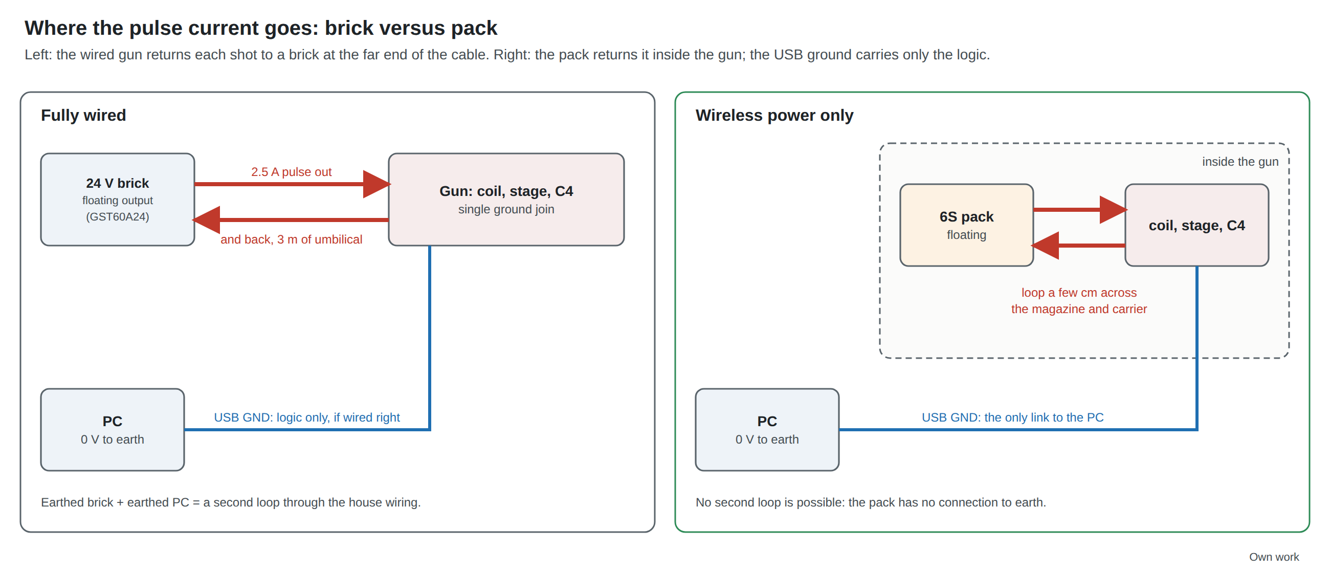
Power Supplies Vol 5 explains why most “the gun resets when it fires” faults are ground shift on the USB link from pulse current sharing a return, not a sagging supply. A pack in the gun removes the mechanism at its root:
- The pulse loop is inside the gun. Pack, fuse, protector, rail switch, J12, C4, the stage and the coil form a loop a few centimetres long. None of its current can flow in the lead, because the pack has no other connection to anything.
- The USB ground is the only link to the PC, and it carries only the logic’s 150 mA. Its steady offset is 41 to 104 mV over 3 m depending on the gauge (Volume 2), and it does not move when the gun fires.
- No second loop through earth is possible. The question of earthed and floating bricks (Power Supplies Vol 5) does not arise: the pack floats.
What stays, because it was never about the cable:
- Layout inside the gun. The pulse loop’s area still radiates and still couples into the camera’s I2C lead and the Pico’s RUN pin. The carrier’s solid ground plane (D34) and the layout rules of Reference Electronics Vol 8 apply unchanged. In the battery magazine, the pack-to-service-connector wiring is part of the pulse loop: twist V_SOL with its return and keep it away from the USB pair.
- The single join. Pulse ground and logic ground still meet at the carrier; the pulse current must still not cross the logic area of the plane.
- The low-side protector’s sneak path. The BQ77905 switches the pack’s negative side, so “any second connection between pack negative and gun ground is a sneak path around the protector” (LiPo Batteries Vol 4, section 4.5). The USB lead ties gun ground to the PC’s, which is why that section names this architecture. With the pack charged out of the gun (LB-5) and nothing else touching pack negative, there is no second connection; a balance lead plugged in while the USB lead is connected would make one. The rule for the battery magazine is the LiPo dive’s: nothing touches pack negative.
- ESD. The lead and its shield are still the path a player’s static discharge takes to the PC. The low-capacitance TVS array on the USB lines that Power Supplies Vol 5 recommends belongs in the battery magazine near the service connector, or on the carrier where the pigtail lands.
Measuring it. The trap in Power Supplies Vol 5, that an instrument’s ground clip can add a loop between two PCs, is milder here, because the gun has no other earth. The first measurement is the same: the difference between the Pico’s ground and the host’s USB shell during a pulse, on two ADP3450 channels. In this architecture it should be a flat line at the DC offset of Volume 2. Any step at the moment of a shot means pulse current has found its way into the logic ground or the lead, and the layout is the place to look.
3.8 Why This, and Why Not the Others
Table 3 — 3.8 Why This, and Why Not the Others
| Row | Pick | Rejected | Why |
|---|---|---|---|
| WP-1 Logic supply | VBUS (bus-powered device) | Pack via buck and ORing (self-powered); pack only | Keeps both USB 2.0 section 7.2.1 rules by construction and needs no firmware change; doubles busy-play runtime. The pack route needs a fork change to gate the pull-up on GP24 (the stock driver forces VBUS-detect on), a power switch, and drains the pack; worth it only on low-power host ports |
| WP-2 Rail-switch enable | LM5060 EN from VBUS (10 kΩ series, 100 kΩ to ground) | Always on; a mechanical switch; a GPIO | Off when unplugged (about 21 µA standby); no switch to forget; a re-plug clears a latched fault; the rail cannot precede the logic. Always-on flattens a 450 mAh pack in about 3 days; a switch can be forgotten; a GPIO costs a pin the carrier lacks and would still need a pull-down |
| WP-3 V_SOL sources | One per magazine: the battery magazine has no brick input | Brick and pack on one rail through the LM5060; back-to-back FETs; LM74700 ideal-diode pair | Mechanical exclusion of the brick-charges-pack path. The plain parallel connection charges the pack at the brick’s 2.5 A through the MOSFET or its body diode; back-to-back FETs still conduct when on; the LM74700 pair is correct but adds two controllers and FETs, kept as the route for a single magazine that must take both |
| ORing for Option B / Stage 2 | LM66100 (Pico module); TPS2116 priority mux (Stage 2 board) | Schottky; DMG2305UX P-FET | Schottky loses 0.3 V and shares the load unpredictably; the P-FET gives VBUS priority, the opposite of what the low-power-port case wants |
Footnotes
-
USB Implementers Forum, Universal Serial Bus Specification, Revision 2.0: section 7.1.5.1 (pull-up “derived from or controlled by the power supplied on the USB cable”), section 7.2.1 (classes of devices; one or five unit loads; “No device shall supply (source) current on VBUS …”), section 7.2.1.5 (self-powered functions). From usb_20_20250603.zip, https://www.usb.org/document-library/usb-20-specification (downloaded 2026-10-19). ↩ ↩2 ↩3
-
TinyUSB,
src/portable/raspberrypi/rp2040/dcd_rp2040.c, master branch:#define FORCE_VBUS_DETECT 1with the comment quoted;dcd_init()settingUSB_USB_PWR_VBUS_DETECT_BITS | USB_USB_PWR_VBUS_DETECT_OVERRIDE_EN_BITSand callingdcd_connect();dcd_connect()settingUSB_SIE_CTRL_PULLUP_EN_BITS. https://github.com/hathach/tinyusb/blob/master/src/portable/raspberrypi/rp2040/dcd_rp2040.c and the same file in https://github.com/adafruit/Adafruit_TinyUSB_Arduino (both master, read 2026-10-19). The copy in the 4.5.4-tusb core the fork pins was not checked. ↩ ↩2 -
Raspberry Pi Ltd, Raspberry Pi Pico Datasheet, sections 4.4 (powerchain; GPIO24 VBUS sense; R10 and R1) and 4.5 (powering Pico; Schottky ORing; the P-FET method and the DMG2305UX). https://datasheets.raspberrypi.com/pico/pico-datasheet.pdf (downloaded 2026-10-19). ↩ ↩2 ↩3
-
Texas Instruments, LM66100 5.5-V, 1.5-A 79-mΩ, Low IQ Ideal Diode With Input Polarity Protection, SLVSEZ8A (June 2019). https://www.ti.com/lit/ds/symlink/lm66100.pdf (downloaded 2026-10-19). ↩
-
Texas Instruments, TPS2116 1.6 V to 5.5 V, 2.5-A Low IQ Power Mux with Manual and Priority Switchover, SLVSFG1A (May 2021). https://www.ti.com/lit/ds/symlink/tps2116.pdf (downloaded 2026-10-19). ↩
-
Texas Instruments, LM5060 High-Side Protection Controller With Low Quiescent Current, SNVS628H (revised December 2019): EN thresholds 2.00 V and 0.80 V, 6 µA pull-down, EN to GND 75 V absolute maximum; VIN current 9 µA typical, 15 µA maximum disabled, 1.4 mA typical enabled; fault latch reset by toggling EN or UVLO. https://www.ti.com/lit/ds/symlink/lm5060.pdf (downloaded 2026-10-19). ↩ ↩2
-
Texas Instruments, LM74700-Q1 Low IQ Reverse Battery Protection Ideal Diode Controller, SNOSD17G (December 2020). https://www.ti.com/lit/ds/symlink/lm74700-q1.pdf (downloaded 2026-10-19). ↩
Comments (0)