Wireless Power Only · Volume 2
The USB Lead — Thin, Flexible, and Nothing but Data and 5 V
What the lead carries, how thin it can be, how long, how many flexes it will survive, where it leaves the gun, and whether a magnetic breakaway belongs on it
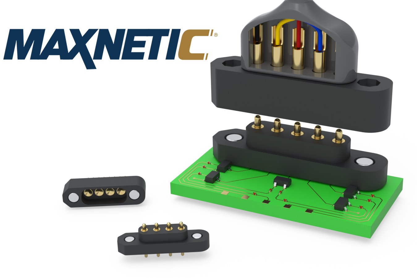
The lead is the one part of this architecture a player handles every minute of a game. In the wired gun it is a sleeve over two cables, one of them a 20 AWG power cable sized for amps of pulse current (Fully Wired Vol 2). Here it carries only USB, at about 150 mA, and can be as light as a mouse cable. This volume decides how light, and what has to be true of it to last.
2.1 What the Lead Carries
Four conductors and a shield:
Table 1 — Four conductors and a shield
| Conductor | Level | Current | Notes |
|---|---|---|---|
| VBUS | 4.75 to 5.25 V at a high-power port | about 100 to 150 mA estimated for the logic (Power Supplies Vol 1); 500 mA is the most a USB 2.0 port must give after configuration | Steady; plus the rail switch’s enable, a few microamps |
| GND | 0 V | the same | The only ground connection between the gun and the PC (Volume 3) |
| D+, D− | differential, 3.3 V swing | — | USB 2.0 full speed, 12 Mbit/s; the RP2040’s USB controller is a full-speed device, so no high-speed pair quality is needed |
| Shield | — | — | Terminated at the PC end only, through the USB-A shell, and folded back at the gun end, as the wired gun’s lead is (WD-4, Fully Wired Vol 5): a printed gun has no chassis, and a gun-end bond would be a second ground path |
What the lead does not carry is as important: no 24 V conductor, no pulse current, no pedal lines unless a pedal is wanted (Section 2.9 covers it). With the pulse return inside the gun, the lead’s ground carries only the logic’s steady current. That is the whole reason it can be thin.
2.2 How Thin: Gauge, Drop and Ground Offset
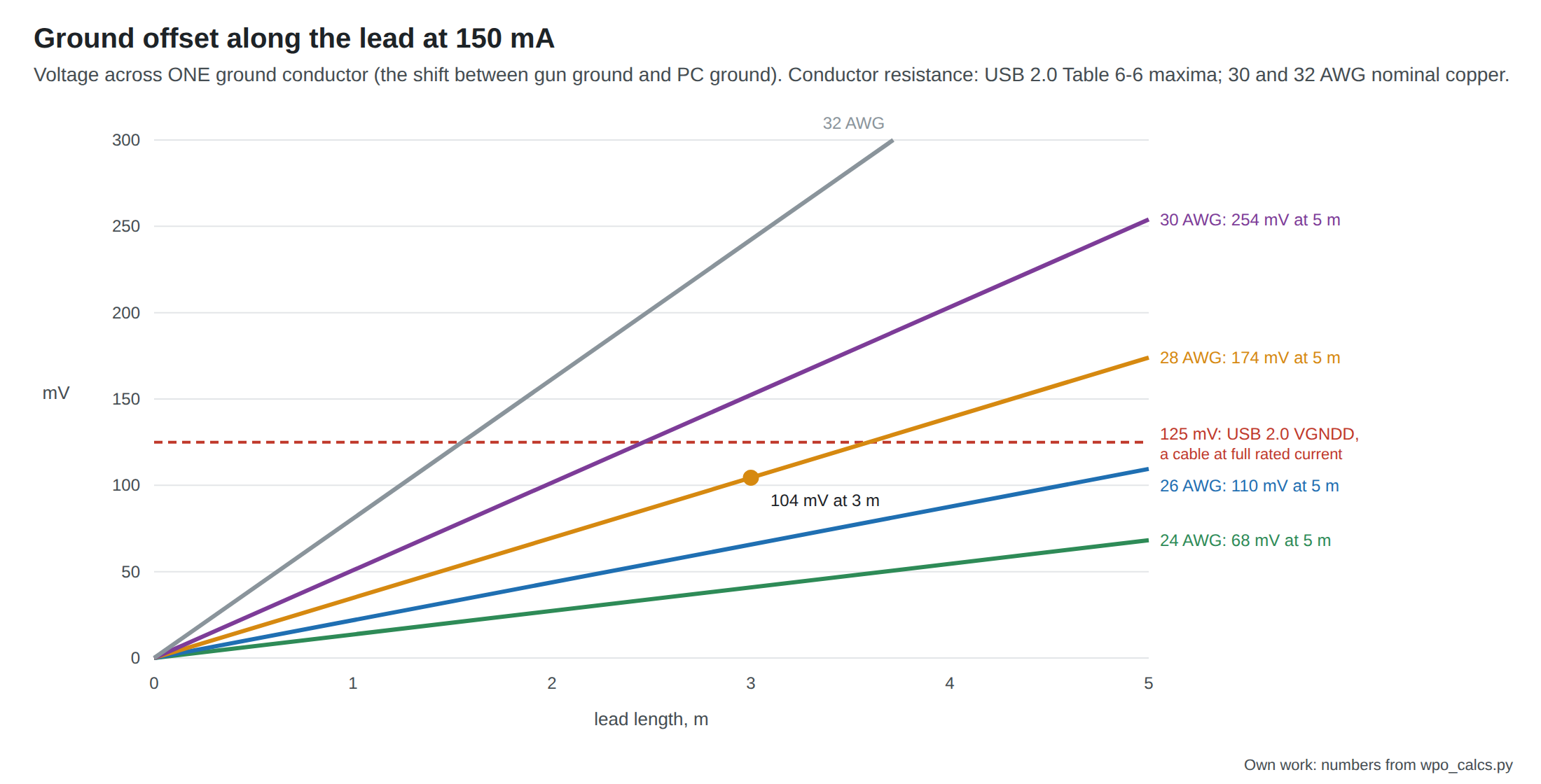
Two voltages matter, and the USB specification bounds both. The VBUS drop decides what voltage reaches the Pico. The ground drop is the offset between the gun’s 0 V and the PC’s 0 V, which every D+ and D− edge is measured against. USB 2.0 allows a detachable cable to drop at most 125 mV on its ground conductor, and the same on VBUS, at its rated current (section 7.2.2), and gives the maximum resistance of each wire gauge (Table 6-6: 23.20 Ω per 100 m for 28 AWG, 9.09 for 24 AWG).1
At the gun’s estimated 150 mA (the numbers are in 04-templates/calc_output.txt):
Table 2 — At the gun's estimated 150 mA (the numbers are in 04-templates/calcoutput.txt)
| Conductors | 3 m: ground offset | 3 m: VBUS + GND round trip | Verdict |
|---|---|---|---|
| 24 AWG power | 41 mV | 82 mV | Ample |
| 28 AWG power | 104 mV | 209 mV | Inside the ground budget at 3 m |
| 30 AWG power | 152 mV | 305 mV | Over 125 mV beyond about 2.5 m |
| 32 AWG power | 242 mV | 484 mV | Over beyond about 1.5 m |
The VBUS round trip barely matters to this gun. The Pico’s VSYS input runs its buck-boost from 1.8 V to 5.5 V (Power Supplies Vol 5), so even half a volt of drop leaves the logic running. The ground offset is the number to respect. It is a steady DC offset, not the volts-per-shot shift a shared pulse return causes in a badly grounded wired gun (Power Supplies Vol 5, section on the OpenFIRE wire-gauge note), and a full-speed receiver’s differential input works over a common-mode range of 0.8 to 2.5 V (USB 2.0 Table 7-7), wide enough to absorb a tenth of a volt. But a lead whose power conductors are thin enough to break the cable budget at 150 mA has no margin for a NeoPixel or a VBUS rumble motor.
The conclusion: 28 AWG power conductors are the floor for a 3 m lead, and 24 AWG is better. The data pair can be 28 AWG or finer; the USB Type-C specification lists 28 to 34 AWG as typical for the USB 2.0 pair and 20 to 28 AWG for VBUS and ground (Table 3-8, informative).2 Cables marked with their gauges, such as the common “28AWG/1P + 24AWG/2C” print on a jacket, say this directly; a lead with no marking is an unknown.
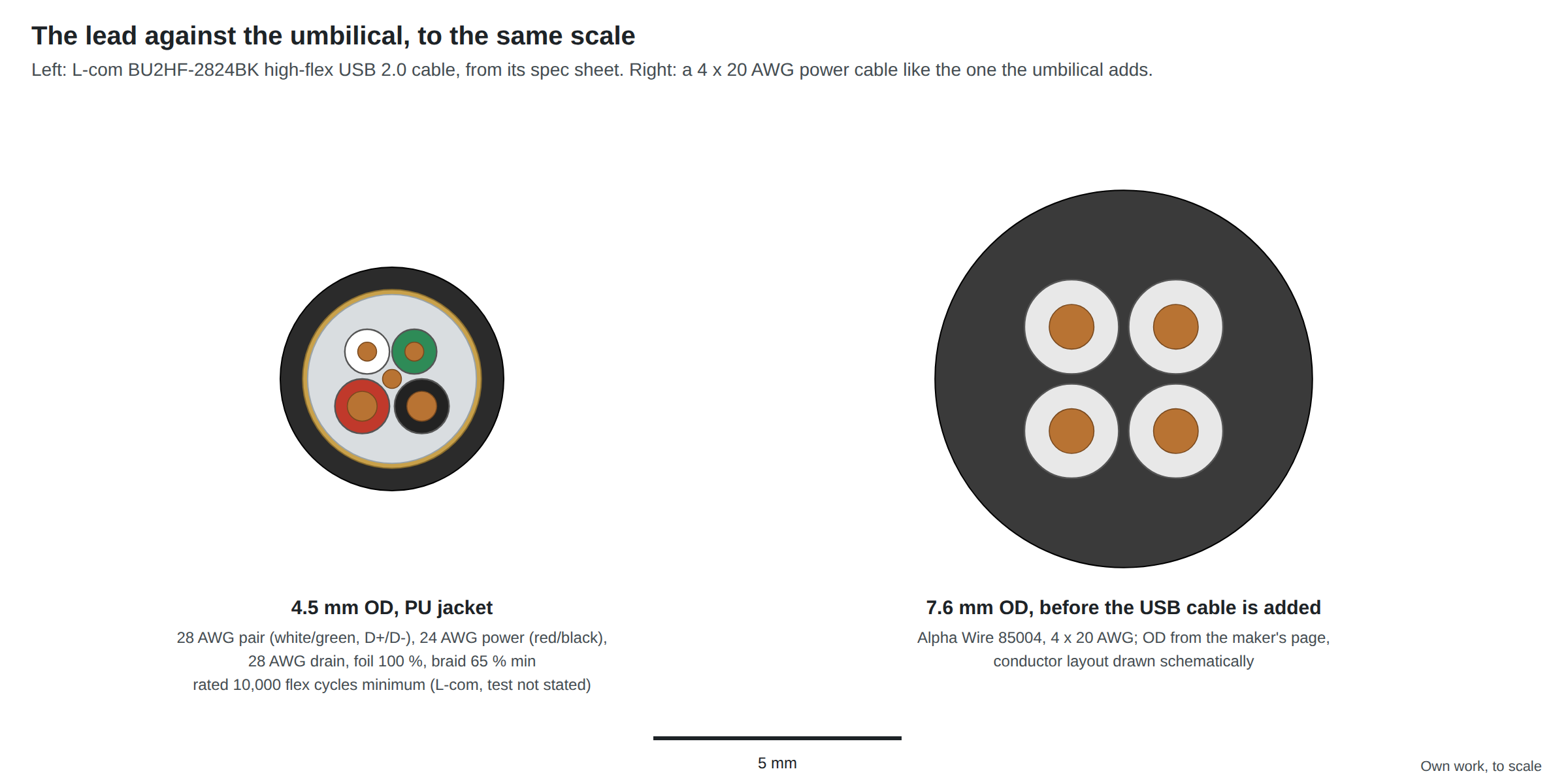
The figure puts the saving in proportion. The wired gun’s umbilical carries a power cable of the 7.6 mm class beside a USB cable, in a braided sleeve (Fully Wired Vol 2). The lead here is the USB cable alone. The USB Type-C specification gives 2 to 4 mm as the typical outside diameter of a USB 2.0 Type-C cable and recommends that “all wires should be stranded, and the cable outer diameter should be minimized as much as possible” for flexibility.2
2.3 How Long
USB 2.0 caps a full-speed cable’s one-way delay at 26 ns and its delay per metre at 5.2 ns, which is where the 5 m maximum for a single cable comes from (Fully Wired Vol 5 works through it).1 Longer runs need a hub or an active extension in the middle, each of which counts as a tier.
For a light gun the practical length is set by the room, not the specification:
- 2 m reaches from a PC beside the screen to a player standing about 2 m back, which is the near end of the playing distances the camera dives work with.
- 3 m gives slack for a player who moves, and is the length the wired umbilical uses.
- 5 m is the specification’s limit, and the ground offset at 28 AWG reaches 174 mV there (Section 2.2).
Recommendation: 3 m. A lead long enough to lie on the floor behind the player is less likely to be stepped on than one taut between the player and the PC.
2.4 Flex Life: What the Ratings Do and Do Not Say
A light-gun lead flexes at two places: where it leaves the gun, every time the gun swings, and wherever it drags on the floor. The failure is almost always at the first: a conductor fatigues inside the jacket just past the strain relief and the gun starts to disconnect intermittently.
The specifications set a qualification floor, not a life:
- USB Type-C, section 3.8.1.4: “No physical damage or discontinuity over 1 ms during flexing shall occur to the cable assembly with Dimension X = 22 mm and 500 cycles in each of two planes” (EIA 364-41, Condition I).2 That is 1,000 flexes in total. A light gun swung once a second exceeds it in a quarter of an hour.
- USB 2.0 (Table 6-7) lists connector durability, 1,500 insertion cycles, and a 40 N cable pull-out, but no flex test for the cable at all.1
Makers who sell flex-rated USB cables state larger numbers. L-com’s high-flex USB 2.0 cables are “rated for 10,000 flex cycles minimum”, and the same page says standard USB cable “fails at approximately 1,000 bend cycles”. Neither figure comes with a test method, bend radius, load or rate, so it is a maker’s claim to compare cables by, not a life to design to.3
What the specification sheets do let a builder compare is construction, which is what flex life follows:
- Strand count. L-com’s BU2HF-2824BK uses 19 strands of 0.003 in for each 28 AWG conductor and 42 strands for each 24 AWG conductor.4 More, finer strands survive more bending at the same gauge.
- Jacket. L-com’s high-flex line uses polyurethane. Silicone-jacketed leads (SparkFun’s, below) drape better; none of those found states a flex rating, so the jacket alone is not evidence of life.
- Diameter. For the same bend, a thinner cable strains its outer strands less, which is the Type-C specification’s reason for minimising diameter.
2.5 Candidate Leads
Prices from the seller’s own page on 19 October 2026.
Table 3 — 2.5 Candidate Leads
| Lead | Conductors | Outside diameter | Flex claim | Price, seller | Verdict |
|---|---|---|---|---|---|
| L-com CAUABHFX-3M, high-flex USB 2.0 A to B, PU jacket, 3 m | 28 AWG pair, 24 AWG power, high strand count | 4.5 mm (bulk cable BU2HF-2824BK) | 10,000 cycles minimum, method not stated | $40.29, L-com | Proposed. The only lead found with a published construction, gauge, diameter and flex claim. The B end is cut off and the lead made captive (Section 2.6). |
| L-com CAUABHFX-2M, the same at 2 m | as above | 4.5 mm | as above | $36.19, L-com | For a small room |
| L-com CAUABHFX-5M, the same at 5 m | as above | 4.5 mm | as above | $49.29, L-com | At the specification’s length limit; only if 3 m is short |
| SparkFun CAB-25629, USB-A to micro-B, silicone, 1 m | not stated | not stated | none stated | $9.95, in stock, SparkFun | Too short; useful as the bench lead and for feel |
| Unmarked “thin” or “ultra-slim” leads | often 28 AWG power or finer, unmarked | 2 to 3 mm | none | — | Rejected unless the jacket states 28 AWG or heavier power conductors (Section 2.2) |
| Coiled USB leads | varies | thick when coiled | none | — | Rejected: the coil’s spring pulls the gun toward the PC and adds weight at the gun end |
| Gaming-mouse “paracord” leads | not stated by the makers found | about 3 to 4 mm | none found | — | Attractive drape, but no maker found publishes gauge or a flex test; a candidate to try, not to specify |
The proposed lead costs four times a generic cable. The extra buys a lead whose construction is known and whose failure point, the gun exit, is designed for flexing. For a kit (D11) the bulk cable is the better route: L-com sells the same construction as bulk cable (BU2HF-2824BK), and a kit lead could be terminated to length with an overmoulded USB-A plug.
2.6 Where the Lead Ends: Captive, With No Connector at the Gun
The wired magazine has a GX16 at the base plate because its umbilical must come off for storage and carries a 24 V pair that must not be mated live (D31). The USB-only lead has neither constraint, and there are three ways to end it at the gun:
Table 4 — The wired magazine has a GX16 at the base plate because its umbilical must come off for storage and carries a 24 V pair that must not be mated live (D31). The USB-only lead has neither constraint, and there are three ways to end it at the gun
| Option | For | Against | Verdict |
|---|---|---|---|
| Captive lead: the cable enters through the base plate, is clamped on a printed boss, and its four conductors and drain are terminated in the magazine’s service connector | No connector at the point that flexes and kicks; the clamp takes all pull; lightest; nothing to mate in the right order | The lead comes off only with the magazine; replacing it means re-terminating four wires | Proposed (WP-5). The magazine is already the removable unit, so a captive lead is in effect a detachable one |
| A USB-C receptacle in the base plate | Any USB-C cable; Type-C’s 10,000-cycle durability rating2 | A USB-C plug in a gun that kicks is a lever on a small receptacle; Type-C’s own wrenching test exists because of it; needs 5.1 kΩ Rd on both CC pins so a C-to-C cable supplies VBUS (USB-C Power Delivery Vol 1); a second board in the magazine | Later, for the Stage 2 custom board, which moves USB onto its own connector anyway (Reference Electronics Vol 8, section 8.10) |
| The GX16 kept, wired for USB only | The same base plate as the wired magazine | A heavy plug on a light lead; and an 8-pin GX16 socket on a battery magazine would accept the wired umbilical and its 24 V | Rejected: it reopens the two-source hazard that the battery magazine exists to close (Volume 3) |
The captive lead is terminated inside the magazine, so the USB pair is unbroken from the PC to the service connector and runs a few centimetres more through it to the Pico’s micro-USB pigtail on the carrier. At full-speed edge rates of 4 to 20 ns, a few centimetres of untwisted pair inside a connector is electrically short; Fully Wired Vol 5 does the signal-integrity arithmetic for the GX16, a much longer discontinuity, and it applies here with margin.
2.7 Strain Relief and the Exit
The magazine’s printed boss and clamp are designed in MP7 Printed Build Vol 5 (P-MP7-6). Four points are specific to a thin lead:
- Clamp the jacket, not the conductors. The clamp should grip the outer jacket over 10 to 15 mm with a smooth bore, so that the braid and the conductors inside carry no tension. A 4.5 mm lead in a clamp sized for the umbilical will slip; the battery magazine needs its own clamp size.
- Give the exit a bend relief. A short tapered sleeve (heat-shrink in two or three steps, or a printed TPU boot) spreads the bend over a few centimetres instead of concentrating it at the edge of the base plate, which is where the conductors fatigue (Section 2.4).
- Point the exit down and slightly back. The lead then falls toward the floor behind the player’s feet, and the gun’s swing bends it in the plane of the boot rather than across it.
- Proof-load it. USB’s own figure for a cable assembly is a 40 N axial pull for one minute without damage (Type-C specification, section 3.8.1.5).2 A printed clamp should hold that much with the lead pulled at the angles a player can produce, before the service connector sees anything.
2.8 Breakaway Connectors
A breakaway is a connector that separates under a pull before anything else breaks. The light-gun case for one is the same as the one that put breakaway dongles on the original Xbox controller “to avoid damage to the console if the cord is tripped over”.5 A player who walks off with a gun on a 3 m lead will pull a laptop or a console off a shelf, or tear the USB-A plug out of a port. There are three places to put one.
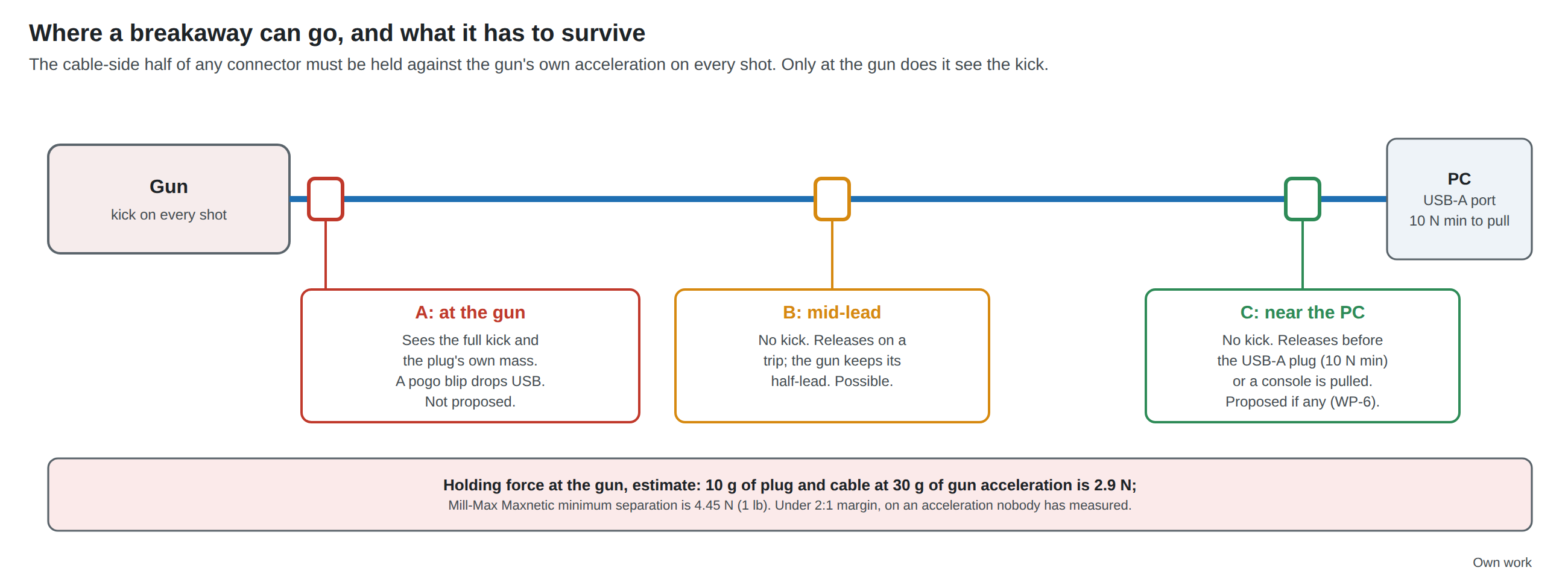
At the gun is the wrong place, for two reasons.
- The kick. The cable-side half of a magnetic connector is held only by its magnets. Every shot accelerates the gun, and the plug half and the cable hanging from it must be accelerated with it by that holding force. The gun’s peak acceleration at the solenoid’s stop has not been measured. A rough bound: the candidate solenoids’ impulses of about 30 to 126 mN·s (Solenoid Recoil Vol 8) on a printed gun of 0.9 to 1.3 kg (MP7 Printed Build Vol 7) are velocity changes of 0.02 to 0.14 m/s, which, delivered over a stop lasting 0.2 to 1 ms, are means of a few g up to about 70 g. Ten grams of plug and cable at 30 g needs 2.9 N. The best-specified magnetic connector found, Mill-Max’s Maxnetic, has a minimum separation force of 1 lb (454 g), 4.45 N, and an average of 1.4 lb (636 g).6 That is under a 2 : 1 margin on an acceleration nobody has measured, and the peak, not the mean, is what separates it.
- The contacts. A USB host decides a full-speed device has gone when the bus sits in single-ended zero for more than T_DDIS, 2 to 2.5 µs (USB 2.0 Table 7-14).1 A spring contact that lifts for a few microseconds during a shot is a disconnect, and the gun re-enumerates. USB’s own connectors are qualified for this: Table 6-7 calls for no discontinuity of 1 µs or longer under a 30 g, 11 ms shock.1 None of the magnetic connectors found publishes a discontinuity figure under shock.
Near the PC is the right place. Nothing there moves with the gun. A breakaway that releases at 4 to 6 N comes apart before a compliant USB-A plug, which USB 2.0 requires to need at least 10 N to extract (Table 6-7), and long before a console or laptop slides.1 The gun keeps its lead; the PC keeps a short stub.
The candidates:
Table 5 — The candidates
| Breakaway | Ratings published | Price, seller, 2026-10-19 | Verdict |
|---|---|---|---|
| Mill-Max Maxnetic, 878-22-004-10-011101 spring-loaded half with 879-20-004-00-011000 target (4 positions) | 7.2 A per pin derated, 20 mΩ, up to 1,000,000 cycles, separation 636 g average, 454 g minimum, self-aligning from 12.7 mm, polarised magnets (Mill-Max) | Not shown on Mill-Max’s page; distributor pages could not be read; price at order time | Proposed for a near-PC breakaway (WP-6), in a small printed housing with the lead clamped either side. The only magnetic part found with a published force and cycle life |
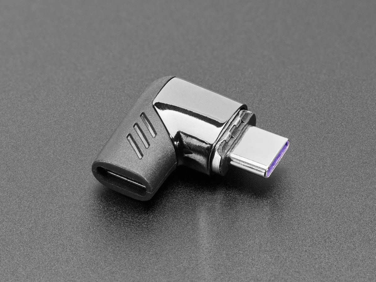
| Adafruit 5521, magnetic right-angle USB-C adapter | ”120W”, passes data (Adafruit tested a MacBook M1 and a Windows PC); no current per pin, force or cycle figure (Adafruit) | $14.95, in stock | Bench trial only: needs a USB-C end on the lead, and nothing about its separation force is stated |
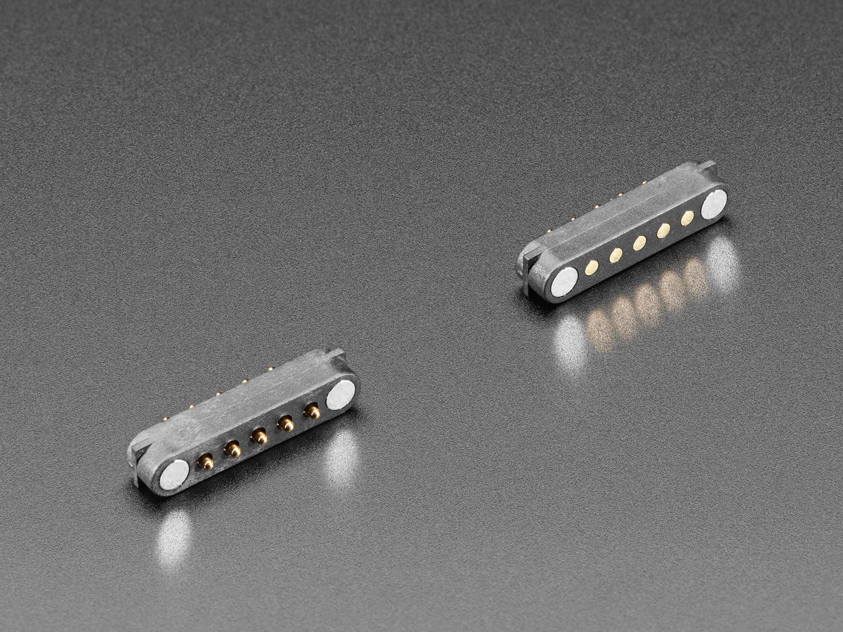
| Adafruit DIY magnetic pogo connectors, 3 to 9 pins (5358, 5359, 5360, 5413, 5467–5470) | Pitch only (0.1 in or 2.2 mm); no current, force or cycle figure (Adafruit) | $5.95 to $10.95, in stock | A cheap way to try the idea; not a specified part |
| No breakaway | — | — | Acceptable for the first build. A desktop PC’s USB-A port is the de facto breakaway; a console or laptop on a shelf is the case that needs one |
A near-PC breakaway puts two more contacts in the USB pair and a few centimetres of untwisted wiring. At full speed that is harmless (Section 2.6); it would not be at high speed, which this gun never uses.
2.9 Why This, and Why Not the Others
Criteria: the ground offset at 150 mA within USB’s 125 mV cable budget at the chosen length; known construction; flex at the gun exit; light; no connector at the point that kicks; a kit route.
Table 6 — 2.9 Why This, and Why Not the Others
| Item | Pick | Rejected | Why |
|---|---|---|---|
| Lead (WP-4) | 3 m high-flex USB 2.0, 28 AWG pair, 24 AWG power, PU jacket: L-com CAUABHFX-3M ($40.29) for the build, BU2HF-2824BK bulk for a kit | Unmarked thin leads; 30–32 AWG power; coiled; 5 m by default | Published gauge, strand count, 4.5 mm diameter and a 10,000-cycle claim; 41 mV of ground offset at 3 m. Thin leads with 30–32 AWG power exceed 125 mV at 2.5 m and 1.5 m; coils pull the gun; 5 m only if the room needs it |
| Gun-end termination (WP-5) | Captive in the battery magazine, clamped, terminated in the service connector | USB-C receptacle at the base plate; GX16 wired USB-only | Nothing to mate or wrench where the gun kicks; the magazine is already the detachable unit. USB-C waits for the Stage 2 board; a GX16 socket would accept the 24 V umbilical |
| Breakaway (WP-6) | None for the first build; if fitted, a Mill-Max Maxnetic 4-position pair near the PC | Any breakaway at the gun; unrated magnetic adapters as the design part | At the gun it must survive every shot’s acceleration on an unmeasured margin and any microsecond dropout disconnects USB; near the PC it releases before a 10 N USB-A plug |
| Pedal | Not on the lead. A pedal needs two more conductors; a gun that wants one is a candidate for the wired magazine, whose umbilical already carries them (CI-7, Fully Wired Vol 1) | A six-conductor lead | A non-USB pair in the lead makes it a custom cable; a USB foot pedal on its own port is the alternative if one is wanted |
Footnotes
-
USB Implementers Forum, Universal Serial Bus Specification, Revision 2.0, section 7.2.2 (voltage drop budget, 125 mV on GND), Table 6-6 (conductor resistance), section 7.1.1.1 and the cable delay of 5.2 ns per metre (26 ns one way), Table 6-7 (durability 1,500 cycles; extraction force 10 N minimum, insertion 35 N maximum; shock 30 g, no discontinuity of 1 µs or more; pull-out 40 N), Table 7-7 (receiver common-mode range 0.8 to 2.5 V), Table 7-14 (T_DDIS 2 to 2.5 µs) and section 7.1.7.3. From usb_20_20250603.zip, https://www.usb.org/document-library/usb-20-specification (downloaded 2026-10-19). ↩ ↩2 ↩3 ↩4 ↩5 ↩6
-
USB 3.0 Promoter Group, USB Type-C Cable and Connector Specification, Release 2.5, March 2026: section 3.3.3 and Table 3-8 (informative wire gauges; “A typical USB 2.0 Type-C cable outer diameter may range from 2 mm to 4 mm”), 3.8.1.3 (durability, 10,000 cycles), 3.8.1.4 (cable flexing, 500 cycles in each of two planes, Dimension X = 22 mm), 3.8.1.5 (pull-out, 40 N for one minute). https://www.usb.org/document-library/usb-type-cr-cable-and-connector-specification-release-25 (downloaded 2026-10-19). ↩ ↩2 ↩3 ↩4 ↩5
-
L-com, “USB High Flex USB 2.0 Cables, Polyurethane Jacket, Type A-B Connectors”: “rated for 10,000 flex cycles minimum”; standard USB cable “fails at approximately 1,000 bend cycles”; 28 AWG data and 24 AWG power conductors; CAUABHFX-03M to -5M, $33.19 to $49.29. https://www.l-com.com/usb-high-flex-usb-20-cables-polyurethane-jacket-type-a-b-connectors (read 2026-10-19). ↩
-
L-com, USB Bulk Cable Specification BU2HF-2824BK, Revision A, 2021-03-11: 28 AWG twisted pair 19/.003 in tinned copper, 24 AWG 42/.003 in; HD-PE insulation; aluminium-polyester tape 100 %; tinned copper braid 65 % minimum; 28 AWG drain; PU jacket 0.018 in; outside diameter 0.177 ± 0.006 in (4.5 ± 0.15 mm); 30 V; 239 Ω/km (28 AWG) and 94.2 Ω/km (24 AWG) maximum. https://www.l-com.com/Images/Downloadables/2D/BU2HF-2824BK-500F_2D.pdf (downloaded 2026-10-19). ↩
-
“Xbox controller”, Wikipedia, Design section: “The Xbox controller features breakaway dongles to avoid damage to the console if the cord is tripped over.” https://en.wikipedia.org/wiki/Xbox_controller (read 2026-10-19). ↩
-
Mill-Max Mfg. Corp., “Maxnetic® Spring-Loaded Connectors”: 878-22-00X-10-011101 and 879-20-00X-00-011000; 2 to 6 positions, 4 mm pitch; 7.2 A per pin, “a de-rated value based on an individual pin in free air”; 20 mΩ; up to 1,000,000 cycles; 1.4 lb (636 g) average and 1 lb (454 g) minimum separation force; engagement from 0.500 in (12.7 mm). https://mill-max.com/products/new/maxneticr-spring-loaded-connectors (read 2026-10-19). ↩
Comments (0)