Fully Wireless · Volume 5
Power — The Logic Rail, What Each Radio Costs, Sleep and Wake, and Surviving the Kick
How the fully wireless gun feeds its logic from the 6S pack, what the ESP32-S3 and Nordic radios each cost in hours of play, why a gun with no cable needs an automatic off, and how to keep the receiver alive and the antenna clear beside a 2.5 A solenoid
5.1 What Is New on the Power Side
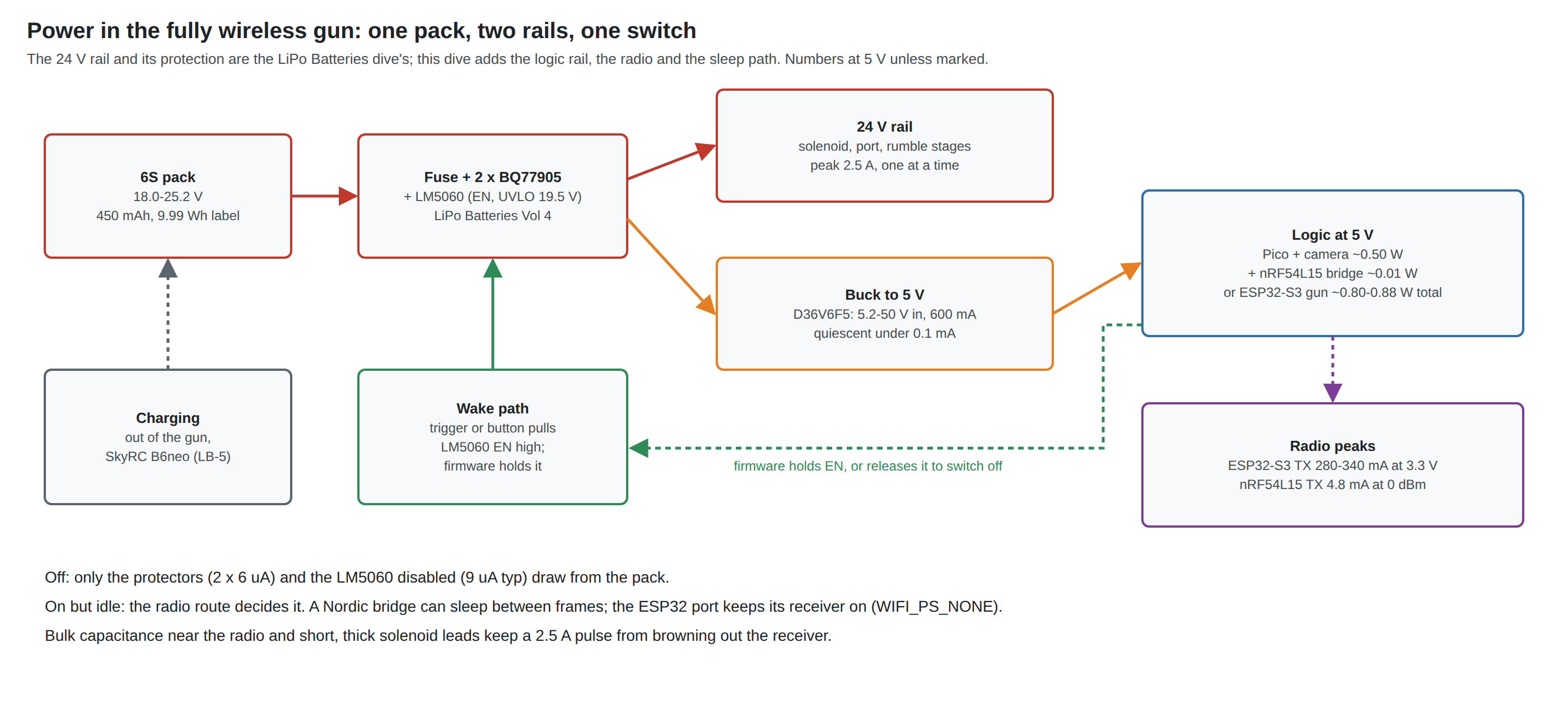
The pack, its fuse, the two stacked BQ77905 protectors, the LM5060 rail switch, the thermistor, the fuel gauge and charging out of the gun are all designed in LiPo Batteries (LB-1 to LB-5). The rule that a brick and a pack never share the recoil rail is Wireless Power Only’s WP-3; the fully wireless gun keeps it trivially, because it has no brick input at all.
What this architecture adds is three things the wireless-power-only gun did not need: the logic runs from the pack, so it needs a regulator and its standby cost counts; nothing unplugs it, so it needs a way to switch itself off; and a radio sits beside the solenoid, so its supply and antenna need protecting from the kick.
5.2 The Logic Rail
LiPo Batteries Vol 3, 3.7 sized the regulator: a buck from the pack to 5 V, for example Pololu’s D36V6F5 (5.2 to 50 V in, 600 mA out, under 0.1 mA quiescent, $5.95 on 19 October 2026), because a linear drop from 22 V to 5 V would burn three times the logic’s own power inside the shell. This volume places it and adds the rules around it:
- After the LM5060, not before. Fed from the switched rail, the buck and everything after it are off when the gun is off, and the LM5060’s under-voltage lock-out (about 19.5 V, LB-4) also protects the pack from being run flat by the logic alone. Before the switch, the buck’s own quiescent current would drain a stored pack (LiPo Batteries Vol 4 lists it as a shelf load for this reason).
- Into VSYS through an ideal diode, never into VBUS. If the gun keeps a USB socket for flashing and configuration, its VBUS and the buck’s 5 V must not meet. Wireless Power Only Vol 3, 3.3 and 3.4 covers the trap (5 V on the Pico’s VBUS pin drives the lead’s VBUS back into the host) and the parts: an LM66100 from the buck into VSYS on a Pico module, a TPS2116 priority mux on a later board (WP-8).
- And the RP2040’s forced D+ pull-up. The same volume found that TinyUSB’s RP2040 driver forces VBUS detection on and enables the D+ pull-up at boot whether or not a host is present. A Pico-based wireless gun runs from its pack, so it inherits this the moment it has a USB socket: plugged into a PC that is off, it drives 3.3 V into the host’s D+. The fix is the fork’s, reading VBUS sense on GPIO24 (on a Pico W or Pico 2 W, the sense line is the wireless chip’s WL_GPIO2 instead; Volume 3, 3.7).
- ESP32-S3 boards take the same 5 V on their 5 V pin and make their own 3.3 V on board; the same never-into-a-host rule applies to their USB socket.
5.3 What Each Radio Costs
The logic load of a cabled gun, a Pico with its camera and inputs, is about 0.1 A at 5 V, 0.5 W (Power Supplies Vol 1). What the radio adds depends entirely on the route:
Table 1 — The logic load of a cabled gun, a Pico with its camera and inputs, is about 0.1 A at 5 V, 0.5 W ([Power Supplies Vol 1](/light-guns/power-and-connectivity/power-supplies/vol-1/)). What the radio adds depends entirely on the route
| Route | What runs | Datasheet figures | Estimated logic load at 5 V | From the pack (85 % buck) |
|---|---|---|---|---|
| No radio (the wireless-power-only reference) | Pico, camera, inputs | — | 0.50 W | 0.59 W |
| B: Pico + nRF54L15 bridge | as above, plus a radio that wakes 209 times a second for about a quarter of a millisecond | nRF54L15 TX 4.8 mA at 0 dBm, RX 3.4 mA at 3 V | 0.51 W (assumes ≤ 3 mA average at 3.3 V for radio and CPU together) | 0.60 W |
| A: ESP32-S3 gun, ESP-NOW | ESP32-S3 replaces the Pico; receiver always on (WIFI_PS_NONE) | ESP32-S3 RX 88 mA (802.11 b/g/n HT20, 3.3 V); CPU 28 to 51 mA single core at 160 to 240 MHz; TX 283 to 340 mA peak, here about 6 mA averaged | 0.80 to 0.88 W | 0.94 to 1.03 W |
Sources: Nordic nRF54L15 product page; Espressif ESP32-S3 Series Datasheet v2.2, Tables 5-7 and 5-9 (Typ1 column; Espressif notes chips with in-package PSRAM “might be higher”). The ESP32-S3 row assumes the Pico’s own ~0.1 W is no longer drawn; all rows are estimates for the bench to replace (Volume 6, W6).
The receiver is the cost. An ESP32-S3 listening continuously draws about 88 mA at 3.3 V, roughly 0.29 W, before it transmits anything; ESP-NOW can sleep between wake windows, but only if the firmware uses Espressif’s wake-window and wake-interval settings, and the port deliberately does not (“Disable power saving for maximum responsiveness”). A Nordic radio sending on demand listens only for its own acknowledgement and is off the rest of the time.
5.4 Hours of Play
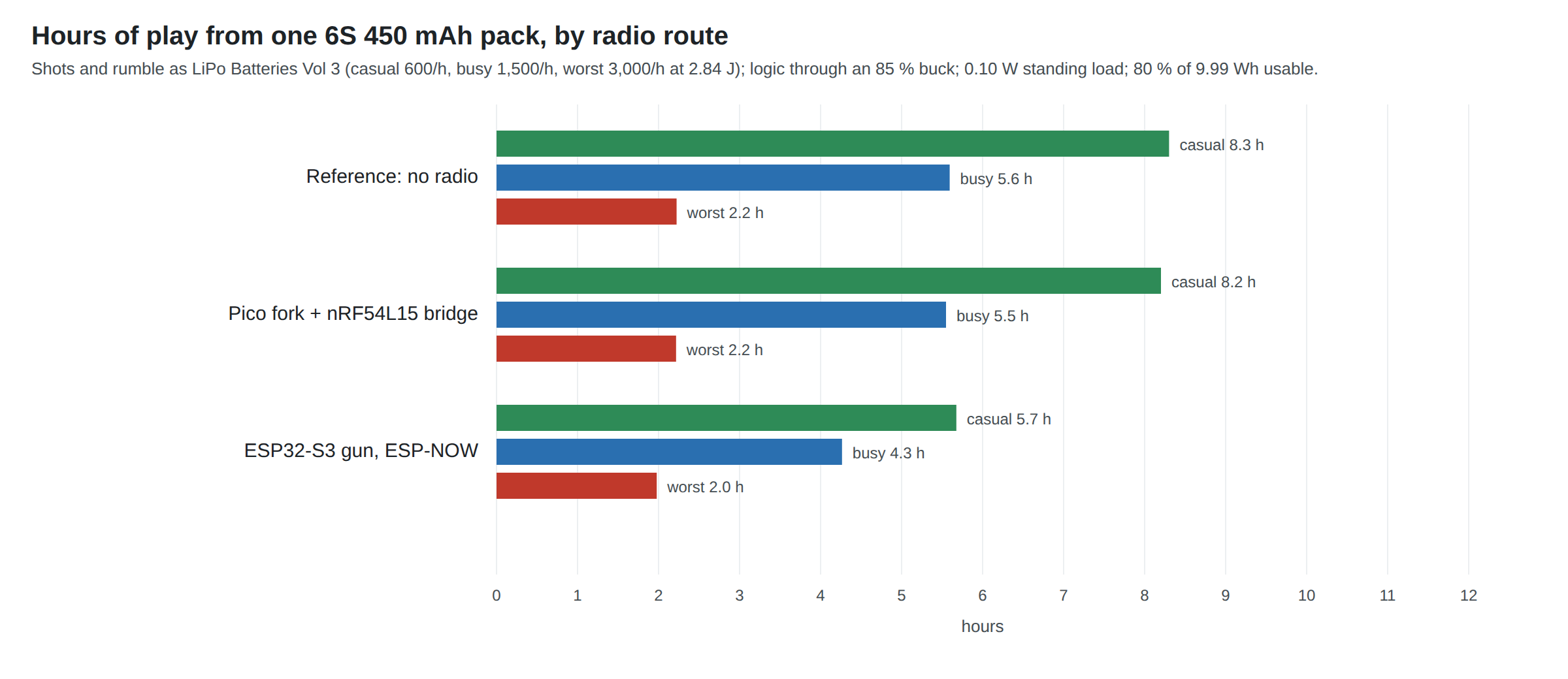
The play patterns are LiPo Batteries Vol 3’s (casual 600 shots an hour, busy 1,500, worst case 3,000 at the unregulated 2.84 J), on 80 % of the GNB pack’s 9.99 Wh. Two corrections are folded in: the logic is now on the pack, and Wireless Power Only Vol 4, 4.2 found a standing load of about 0.10 W while the rail is on (the LM5060 itself, the rumble stage’s DRV8251A held awake by its braked inputs, and the gauge divider), which brings the LiPo dive’s 9.3 / 6.0 / 2.3 hours to 8.3 / 5.6 / 2.2.
Table 2 — 5.4 Hours of Play
| Route | Casual | Busy | Worst | Switched on, idle |
|---|---|---|---|---|
| No radio (reference) | 8.3 h | 5.6 h | 2.2 h | 11.6 h |
| B: Pico + nRF54L15 | 8.2 h | 5.5 h | 2.2 h | 11.4 h |
| A: ESP32-S3, ESP-NOW | 5.7 to 6.1 h | 4.3 to 4.5 h | 2.0 h | 7.1 to 7.7 h |
Either route lasts an evening on the smallest pack. The Nordic radio costs a few minutes; the ESP32’s always-on receiver costs about a third of a casual evening. That is not a reason to reject route A for the trial, but it is one more reason the kit route is B, and it doubles the importance of the next section: an ESP32 gun left switched on in a drawer is flat in about seven hours.
5.5 Off, Idle and Wake
A cabled gun turns off when it is unplugged, and the wireless-power-only gun ties its rail switch to VBUS so that it does too (WP-2). A fully wireless gun has nothing to unplug. Three states are worth designing for:
Table 3 — A cabled gun turns off when it is unplugged, and the wireless-power-only gun ties its rail switch to VBUS so that it does too (WP-2). A fully wireless gun has nothing to unplug. Three states are worth designing for
| State | What is powered | Draw from the pack | How long a 450 mAh pack lasts |
|---|---|---|---|
| Off | Only the protectors (2 × 6 µA) and the disabled LM5060 (9 µA typical, 15 µA maximum) | about 21 µA, 0.5 mW | Years by this load; the pack’s own self-discharge and the storage rules of LiPo Batteries Vol 6 govern instead |
| On, idle (no camera points, no trigger) | Everything | about 0.70 W (route B) to about 1.1 W (route A) | 11 to 7 hours |
| Playing | Everything | Section 5.4 | Section 5.4 |
The proposal (WL-6): a soft power latch on the LM5060’s enable, with an automatic off. LiPo Batteries Vol 4 already puts the gun’s power switch on the LM5060’s EN pin. Replace the slide switch with a momentary button that pulls EN high (EN is rated to 75 V and switches on above 2.0 V, so it can be pulled from the pack through a resistor), and give the controller a GPIO that holds EN high through a diode once it has booted. The firmware then owns the off: after a set time with no trigger, no buttons and no IR points in view (ten minutes is a starting value, not a measured one), it releases EN, and the whole gun, logic included, drops to the 21 µA of the “off” row. The button also serves as a deliberate off with a long press. Michael gets a gun that cannot be left on; the pack gets the LM5060’s under-voltage lock-out as a backstop. It is a fork change (an idle timer and one pin) for route B, and a change to a firmware the project does not maintain for route A, so on the ESP32 trial the slide switch stays.
Lighter sleep while on is possible but secondary. On route B the Nordic part can sleep between reports by itself; the Pico and the camera, which dominate, could drop the camera rate when no points are seen, which is fork work for later. On route A, ESP-NOW’s wake window would cut the receiver’s 0.29 W only at the cost of latency, which is why the port turns it off.
Wake on the trigger would be nicer than a separate button. The trigger is a Hall sensor or microswitch on the logic side, unpowered when the gun is off; a second pole on a microswitch trigger, diode-ORed onto EN, would do it. That depends on Controls and Inputs’s trigger choice and is left as a question.
5.6 Keeping the Radio Alive Through a Solenoid Pulse
The ESP32 port’s troubleshooting list says it plainly: “use solenoid power wires of at least 24 AWG, as thinner wires can cause disconnections.” The mechanism is not mysterious:
- A shared return shifts the radio’s ground. A recoil pulse draws up to 2.5 A from the pack (LiPo Batteries Vol 3). If that current returns to the pack along any conductor the logic also uses for ground, the logic’s ground rises by I × R of the shared section: 2.5 A in 100 mm of 28 AWG hook-up wire (about 21 mΩ) is about 53 mV; in a long thin lead or a poor crimp, hundreds. A radio transmitting at that moment, or the UART between the Pico and a radio bridge, sees it as noise.
- The radio’s own peak. An ESP32-S3 transmitting draws up to 283 to 340 mA at 3.3 V. On a small board’s LDO, with its supply already dipping from the shared-ground shift, a coincident transmit can reset the chip, which the user sees as a disconnection. A Nordic radio’s 5 mA peak makes this far less likely.
- The chopper. The regulated DRV8251A stages switch the coil current at their chopping rate. Their harmonics are far below 2.4 GHz, but the fast edges radiate broadband; an antenna lying along the solenoid leads couples them in.
The defences are the ones the carrier already has, applied with the radio in mind: one solid ground plane on the four-layer carrier (D34, Reference Electronics Vol 8), with the solenoid’s return path short and away from the radio’s; short, thick solenoid leads (at least 24 AWG, as the port says, shorter is better); bulk capacitance at the logic regulator’s output and at the radio board’s supply pin; and the antenna away from the leads (Section 5.7). On the bench, the test is direct: the radio board’s 3.3 V on one ADP3450 channel and the coil current on another during full-rate autofire, while the link-loss counter runs (Volume 6, W7).
5.7 Where the Antenna Goes
Every source agrees on the rule and none gives a number for a gun: Espressif’s port says to “keep a small clear area around the board’s antenna … do not route wires over it or right next to it, and do not cover it with metal”; Raspberry Pi’s Pico 2 W datasheet says the antenna “should be in free space”, that “putting metal under or close by the antenna can reduce its performance”, and gives a 14 × 9 mm keep-out. A printed MP7 shell is plastic, so the shell itself is not the problem; the solenoid, its leads, any metal rail or weight, the pack and the player’s hand are.
For the printed MP7 (D35), the candidate places, to be compared by received signal strength on the bench:
Table 4 — For the printed MP7 (D35), the candidate places, to be compared by received signal strength on the bench
| Place | For | Against |
|---|---|---|
| Top of the receiver, above the bore line, antenna end pointing forward | Clear line to the screen and the dongle; away from the hand | Near the camera and its cable; near the recoil mechanism if it runs along the top |
| Stock or rear of the receiver | Far from the solenoid | The player’s body is between it and the screen when shouldered |
| Magazine | Already the battery’s place (LB-6) | Inside the hand; next to the pack |
| A remote antenna on the XIAO’s U.FL socket | The module can sit anywhere and the antenna go to the best spot | Only route B’s XIAO has the socket among the boards here (LILYGO sells a K194-01 external-antenna dongle) |
5.8 Why This, and Why Not the Others
Table 5 — 5.8 Why This, and Why Not the Others
| Choice | Pick | Rejected, and why |
|---|---|---|
| Where the logic regulator sits | After the LM5060, from the switched rail | Before it: the buck’s quiescent current drains a stored pack and the UVLO no longer protects the pack from the logic |
| Logic regulator | Buck to 5 V (D36V6F5, LiPo Vol 3) into VSYS through an ideal diode (WP-8 parts) | Linear: ~1.7 W of heat; into VBUS: back-feeds the host (WPO Vol 3) |
| Radio, on power alone | Nordic (route B), ~0.01 W | ESP32-S3 receiver always on, ~0.3 W, about a third of a casual evening |
| On-off | Soft latch on LM5060 EN with a firmware auto-off (WL-6) | Slide switch alone: a gun left on is flat overnight; VBUS-enable (WP-2): there is no VBUS |
| Ground and leads | Solid plane (D34), short ≥ 24 AWG solenoid leads, bulk capacitance at the radio | Thin leads sharing a return with the logic: the port’s own documented cause of disconnections |
| Antenna | Clear of the solenoid, leads and hand; chosen by RSSI on the bench | Wherever the board fits |
Sources
- Espressif, ESP32-S3 Series Datasheet v2.2, Tables 5-7, 5-8, 5-9 — https://documentation.espressif.com/esp32-s3_datasheet_en.pdf (fetched 2026-10-19).
- Nordic Semiconductor, nRF54L15 product page (read 2026-10-19).
- Alessandro Satanassi, OpenFIRE-Firmware-ESP32,
lightgun/src/README.md(“Common problems”),lightgun/README.md,shared_lib/OpenFIRE_Wireless/ESP32/OpenFIRE_Wireless.cpp(read 2026-10-19). - Raspberry Pi, Raspberry Pi Pico 2 W Datasheet (antenna keep-out and placement) (fetched 2026-10-19).
- Texas Instruments, LM5060 data sheet, figures as quoted in Wireless Power Only research notes and LiPo Batteries Vol 4 (EN thresholds, 75 V EN maximum, 9 µA disabled quiescent current).
- This dive’s model:
04-templates/wireless_calcs.py,calc_output.txt.
Comments (0)