Our Firmware · Volume 5
Testing the Fork — Host Tests, the ADP3450 on the Bench, and a Checklist Before Every Release
Upstream compiles but does not test; the fork has to. What can be proved on the workstation with no hardware, how to instrument the firmware without spending a pin, the seven bench captures on the Analog Discovery Pro ADP3450 that cover every change, the serial flood and soak tests, and the release checklist
5.1 What upstream tests, and what it does not
OpenFIRE’s continuous-integration workflow, read at v6.2, runs on every push and pull request and does one thing: it compiles the firmware for each supported board and keeps the UF2s. Nothing in the repository runs the code. The ESP32 port goes further on one side: its web configuration app has sixteen files under webapp/tests, including a mock firmware and protocol and calibration-UI tests; but the firmware’s own lightgun/test directory held only a README on 19 October 2026. That is normal for hobby firmware, and it means the findings in Open-Source Firmware and Aiming Maths were found by reading, not by failing tests.
A fork that changes the aiming maths, the trigger and two power stages cannot work that way. Three levels of test cover it:
Table 1 — A fork that changes the aiming maths, the trigger and two power stages cannot work that way. Three levels of test cover it
| Level | Runs on | Proves | When |
|---|---|---|---|
| Host | the Linux workstation, no hardware | the maths and the state machines give the right answers | every commit to a change branch |
| Bench | a Pico (or the carrier) with the ADP3450 attached | timing, sequencing and bus behaviour on real silicon | before a change branch is merged |
| Release | the whole gun at the screen | it works as a light gun, for hours | before a release is tagged |
5.2 Host tests: the maths and the state machines
The parts of the fork that are pure computation can be compiled as ordinary C++ on the workstation and fed inputs whose right answers are known:
- The homography and calibration map (AM-1, AM-2, AM-9, AM-10). The Aiming Maths dive’s simulation,
aim_maths.py, already generates synthetic camera points for known gun poses and computes what the cursor should be. Exporting those cases as test vectors turns the dive’s numbers into a regression test: v6.2’s code should reproduce v6.2’s errors (4 mm at the edge for 30 mm bars, for instance), and the fork’s code should remove them. - The lens correction (AM-4), once the bench sweep provides coefficients.
- The filters (AM-8) on recorded or synthetic cursor traces: jitter at rest and lag on a sweep, the two numbers the dive uses.
- The off-screen hysteresis (AM-7) on a trace that dithers across the edge.
- The trigger thresholds (P-RE7, CI-5): calibration refusing a bad break, the fault band reading as released.
- The output sequencer and hold-open (D16, ME-3, MR-6) driven by scripted event sequences (trigger,
FDAxvalues, reload, time) and checked against the rule that EJECT never rises while SOL is high or decaying, that a hold ends at its limit, and that a rumble start waits.
Two design rules make this possible. The new code is written as functions that take values and return values, with the reading of pins and the writing of outputs at the edges; and the time source is passed in rather than read from millis() inside the logic, so a test can step time.
5.3 Instrumenting the firmware without a spare pin
Bench timing needs the firmware to mark events on a pin the logic analyser can see: “frame processed”, “trigger crossed”, “report queued”. The kit-camera pin map uses all 26 user GPIO with none spare (Reference Electronics, P-RE19), and the stopgap map has one, GP15.
The Pico has a pin the budget never counts: GP25 drives the on-board LED and is not brought out to the header (OpenFIRE’s board header marks it unavailable for that reason, and its rpipico2 entry is identical; Reference Electronics Vol 2). A probe on the LED’s resistor reads it. The fork’s debug build (a compile-time define, never in a release) uses GP25 as its event pin, and GP15 as a second one on the stopgap board. A one-instruction pin toggle costs nanoseconds, so the measurement does not disturb what it measures, unlike a serial print.
The serial debug output that v6.2 already has (DEBUG_SERIAL, PRINT_VERBOSE in OpenFIREDefines.h) stays for what it is good at: values, not timing.
5.4 Seven bench captures on the ADP3450
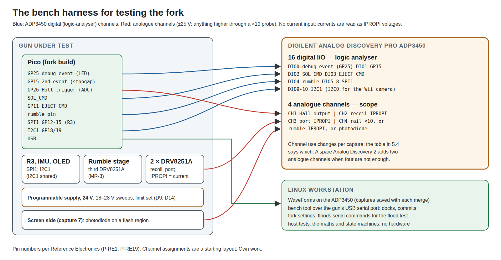
The lab’s instrument for this project is the Digilent Analog Discovery Pro ADP3450 (decision D9): four single-ended analogue channels (14-bit, at least 55 MHz, up to 125 MS/s, ±25 V) and 16 digital I/O, as Digilent’s specification was read for Solenoid Recoil Vol 6 and Reference Electronics Vol 7. Those dives also set the probing rules (no current input, so currents are read as the DRV8251A’s IPROPI voltage; anything above 25 V through a ×10 probe). Seven captures cover every change in Volumes 2 and 3:
Table 2 — The lab's instrument for this project is the Digilent Analog Discovery Pro ADP3450 (decision D9): four single-ended analogue channels (14-bit, at least 55 MHz, up to 125 MS/s, ±25 V) and 16 digital I/O, as Digilent's specification was read for [Solenoid Recoil Vol 6](/light-guns/recoil-and-force-feedback/solenoid-recoil/vol-6/) and [Reference Electronics Vol 7](/light-guns/building-the-electronics/reference-electronics/vol-7/). Those dives also set the probing rules (no current input, so currents are read as the DRV8251A's IPROPI voltage; anything above 25 V through a ×10 probe). Seven captures cover every change in Volumes 2 and 3
| # | Capture | Channels | Proves | Changes |
|---|---|---|---|---|
| 1 | Loop and frame timing | debug pin toggled per camera frame and per input poll | the fork has not slowed core 0’s 209 Hz camera loop or core 1’s polling | every change in the hot files |
| 2 | Trigger latency | analogue: Hall output; digital: debug pin at the trigger event | threshold crossing to event in microseconds, not the stock filter’s milliseconds | P-RE7, CI-5, CI-6 |
| 3 | Camera bus | SPI (CS, SCK, MISO, MOSI) or I2C0, decoded by the logic analyser | the PAJ7025R3 driver’s transactions, product ID 0x7025, frame period | PixArt driver, ES-1, ES-2 |
| 4 | Peripheral bus | I2C1 (GP18/19) decoded | IMU FIFO drains are not starved by OLED redraws in autofire | D36, D37 |
| 5 | Two stages | digital: SOL_CMD, EJECT_CMD; analogue: both IPROPI | EJECT never high while SOL is high or decaying; the forced-overlap build is held off by Q4 | D16, ME-3 |
| 6 | Rumble | digital: rumble pin; analogue: rail, rumble IPROPI | 25 kHz, duty cap; no start inside a pulse; the Wii camera clock unchanged | MR-4, MR-6 |
| 7 | End to end | debug pin when a USB report with a changed position is queued; a photodiode on the screen | trigger or motion to screen | AM-8, and the latency chain of Aiming Maths Vol 7 §7.6 |
The sibling dives’ own bench procedures (the solenoid rig, the port cassette test, the IMU tests, the PixArt tests) are run as written; this table is what the fork adds on top, so that each merge has a capture attached.
5.5 Serial flood and soak
Serial flood. The pinned core exists because of a serial crash under fast incoming data (TinyUSB issue #293). The test, from Open-Source Firmware Vol 7 §7.8, is a script on the workstation that floods the gun’s serial port with force-feedback commands while it is in use. It runs on every release, because the fork adds serial handling (the bench tool’s settings, FDAx driving the hold-open), and on any branch that changes the core.
Soak. One hour of autofire with the recoil, port and rumble enabled and the IMU running, logging the TMP36 readings, any brick trip (the rail on an analogue channel) and any USB disconnect on the host. The temperature cut-outs (OSF-3 and the port coil’s limit) must act during it, not merely exist.
Upgrade. Flash the previous release, set every fork setting with the bench tool, flash the new release, read the settings back (Volume 4 §4.6).
5.6 The release checklist
Table 3 — 5.6 The release checklist
| # | Check | Pass |
|---|---|---|
| 1 | Clean build from the source archive with the pinned toolchain | UF2 matches the release’s UF2 (or the difference is explained) |
| 2 | Host tests | all pass |
| 3 | Captures 1, 2, 5 and 6 (and 3, 4 if the camera or I2C1 code changed) | within the limits recorded in the change cards |
| 4 | Stock App docks, calibrates, runs its tests, commits settings | no errors; fork settings survive a commit from the stock App |
| 5 | MiSTer and QMamehook find the gun | gun recognised (VID 0xF143 and “OpenFIRE” kept) |
| 6 | Serial flood | no freeze in 10 minutes |
| 7 | Soak | one hour, no trip, no disconnect, cut-outs acted |
| 8 | Upgrade path | settings survive, or the upgrade note says they do not |
| 9 | Calibration and aim at the screen | edge and centre targets within the fork’s expected error at two distances |
| 10 | Manifest, change log, test record written | in the release |
Item 4 matters more than it looks: the stock App commits only the names it knows (Volume 1 §1.5), so the test confirms that a commit from the App leaves the fork’s own settings untouched in flash.
5.7 Why this, and why not the others
FW-6, test strategy (proposed here). The criteria: catches regressions before they reach the gun; uses the lab’s instruments (D9); costs little to repeat at every upstream merge.
Table 4 — 5.7 Why this, and why not the others
| Option | Verdict | Reason |
|---|---|---|
| Host tests for the maths and state machines, ADP3450 captures for timing, release checklist | Pick | Each kind of fault is caught where it is cheapest: wrong numbers on the workstation, wrong timing on the bench, wrong behaviour at the screen |
| Compile-only, as upstream | Rejected | Proves nothing about behaviour; the v6.2 findings were all found by reading |
| Bench only, no host tests | Rejected | Every maths regression would need a calibrated gun and a screen to see |
| Serial prints for timing | Rejected for timing | A print takes far longer than the events being timed and shifts them; kept for values |
| A hardware debugger (SWD) as the main tool | Complement, later | Good for stepping through a fault; not a regression test. No SWD probe is listed in the lab; not needed for this plan |
| A full hardware-in-the-loop rig (instrument scripts driving the gun automatically) | Later | The ADP3450’s scripting would allow it; worth building once the captures are stable and repeated at every release |
5.8 What could not be verified
- The capture limits are not yet numbers; each will be set from the first bench run of each change.
- That probing the LED resistor gives a clean enough edge for timing; not tried on a board in hand.
- The ADP3450’s protocol decoding of SPI and I2C at the rates used was not tried for this dive.
Sources
- TeamOpenFIRE,
OpenFIRE-Firmwarev6.2,.github/workflows/arduino-cli-builds.yml,OpenFIREmain/OpenFIREDefines.h— read 2026-10-19. - Alessandro Satanassi,
OpenFIRE-Firmware-ESP32,lightgun/test/(README only) andlightgun/webapp/tests/(16 files) — snapshot 2026-10-19. - Aiming Maths and Calibration dive,
04-templates/aim_maths.pyand Volumes 4, 6, 7. - Solenoid Recoil Vol 6 and Reference Electronics Vol 7 (the ADP3450’s specification as read there); Moving Ejection Port Vol 6; Positional and Inertial Vol 6; Experimental Sensing Vol 2; Motors and Rumble Vols 4, 6, 7.
- Open-Source Firmware dive, Volume 7 §7.8 (serial flood test).
- Category decision log, rows D9, P-RE19.
Comments (0)