Our Firmware · Volume 3
The Change List, Part 2 — Trigger, Recoil, Ejection Port, Rumble, Display and the v6.2 Fixes
The output side of the fork: the analog Hall trigger and its three-point calibration, a pulse ended at landing, the rule that the recoil and port stages never fire together, the hold-open state machine, quiet rumble that waits its turn, the ammo count, the vendor ID, and what to do with each of the twelve v6.2 findings
The cards follow the format of Volume 2 §2.1: source, change, reason, risk, test.
3.1 The trigger: P-RE7, CI-5, CI-6
The trigger is a Hall-effect sensor from the start (decision D8), the Texas Instruments DRV5056A4 in the analog version (Reference Electronics Vol 4 §4.6, P-RE5). Stock OpenFIRE cannot read it: its list of pin functions has a digital “Trigger” and only three analog entries, two stick axes and the temperature sensor. Three rows turn it into a trigger.
P-RE7 — the analog trigger
- Source: Reference Electronics Vol 4 §4.6.
- Change: a new pin function, an analog trigger on GP26 (ADC0), added at the bottom of the shared header’s input list (Volume 1 §1.5); the reading is compared with thresholds and fed into the button state as the trigger bit, so everything downstream (calibration steps, autofire, recoil) sees an ordinary trigger. A reading below about 0.5 V or pinned at full scale is a fault and reads as released, never as held. On a Pico 2 the pin’s digital input is disabled explicitly (the RP2350’s erratum E9 text asks for it). Thresholds avoid the RP2040’s ADC DNL spikes at codes 512, 1,536, 2,560 and 3,584 (erratum RP2040-E11).
- Reason: no other way to use the sensor the owner chose.
- Risk: low in itself; the work is in CI-5.
- Test: sweep the magnet on a caliper and log the count and the trigger bit; unplug the sensor with the gun live and confirm the trigger reads released.
CI-5 — fire at the felt break
- Source: Controls and Inputs Vol 4 §4.5.
- Change: calibration records three counts, rest, break and full; press is the break plus a small margin, release is the break minus the hysteresis. The fixed 50 % / 40 % of P-RE7 remain the defaults before calibration.
- Reason: with a detent in the trigger, a percentage of travel puts the shot wherever the printed notch did not; the break count puts it where the finger feels it.
- Risk: a calibration done badly (break recorded at rest) makes a hair trigger. The routine refuses a break that is not well clear of both rest and full.
- Test: twenty pulls, logging the count at which the shot fires against the count at the detent crest, measured by a slow pull on the bench.
CI-6 — no button-library debounce for the trigger
- Source: Controls and Inputs Vol 5 §5.6.
- Change: the analog trigger’s state bypasses
LightgunButtons’ filter and lockout; its hysteresis is its debounce (about 150 counts against about 4 of noise). - Reason: a contactless sensor cannot bounce, so the library’s 32-read filter and 15 ms lockout are pure delay on the one input where delay matters.
- Risk: low. Other inputs keep the library’s filter unchanged.
- Test: ADP3450, one digital channel on a test pin the debug build toggles at the trigger event and one analog channel on the sensor output; latency from threshold crossing to event, fork against stock with the digital DRV5023 in the same footprint.
3.2 Recoil: the pulse ended at landing
- Source: Solenoid Recoil Vol 8; decision D13 (SR-2).
- Change: almost none. With the regulated DRV8251A stage the current is set in hardware by the VREF divider (Reference Electronics Vol 5 §5.12), so the firmware’s only job is the pulse length, and v6.2 already has it as the named setting
SolOn. The landing time measured on the bench, plus 2 ms, becomesSolOn. - Reason: the kick stops growing once the plunger lands; every millisecond after it is heat (Solenoid Recoil models about 80 % of a fixed 45 ms pulse as waste).
- Risk: v6.2’s timing is in whole milliseconds (
millis()), adequate for a landing at 6–10 ms. A sub-millisecond trim would mean moving the feedback timer to microseconds, which is not proposed. - Test: Solenoid Recoil Vol 8’s trimmed-pulse step on the ADP3450.
This is the best kind of change: a decision that removes code rather than adding it.
3.3 Two stages, never at once: D16
- Source: decision D16; Reference Electronics Vol 5 §5.13 (P-RE21); Moving Ejection Port Vol 4.
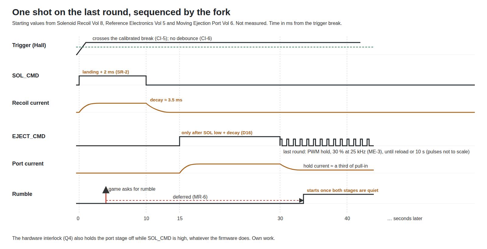
- Change: a new output, EJECT_CMD on GP11, driving the second regulated stage. It may rise only when SOL_CMD has been low for at least the measured decay time, and SOL_CMD wins any conflict. If the next shot is due before the port is home, the port stroke is skipped, never the kick.
- Reason: the brick is sized for one stage (GST60A24 class). Reference Electronics estimates the decay of a 2 A current in the model’s 44 mH coil at roughly 3.5 ms with the coast release.
- Risk: this is the only change where a firmware bug could stress hardware. The board’s interlock transistor Q4 holds the port stage’s input low while SOL_CMD is high, so a fork bug that raises both cannot fire both; the reverse (recoil during the port’s tail) is left to firmware by design.
- Test: Moving Ejection Port Vol 6 step 5: a hundred shots with both enabled, confirming on the digital channels that EJECT_CMD never rises while SOL_CMD is high; then a test build that forces the overlap, to prove Q4 holds.
3.4 The ejection port and hold-open: ME-3
- Source: Moving Ejection Port Vol 2 (the state machine), Vol 4 “What the fork has to do”, Vol 6 “Starting values for the fork”.
- Change: after each kick (and after 3.3’s delay), a port pulse ended at the port’s arrival plus 2 ms. On the last round, a state machine: CLOSED → CYCLING → HELD OPEN (EJECT_CMD switched to PWM at a hold duty) → RELEASING on a reload, the hold limit, or the port coil’s temperature → CLOSED. “Last round” comes from the game, through the
FDAxserial command OpenFIRE already parses for its OLED (the v6.2 parser stores it withconstrain(serialAmmoCount, 0, 99)), or from the gun’s own shot count against a set magazine size, off by default. - Reason: the owner’s realism brief for the MP7 (category plan, decision 4: kick only, plus a moving ejection port); a port that stays back on an empty magazine is the detail that sells it.
- Risk: three. A held coil is a heater, so the hold limit (10 s to start) and the temperature cut-out (a second TMP36 on GP27, Reference Electronics Vol 2) are mandatory, the same lesson as v6.2 finding 4. The own-count mode will be wrong whenever the game’s idea of a magazine differs, which is why it is off by default. And PWM hold on the DRV8251A is untried: the chop frequency is set by the PWM, not the coil.
- Test: Moving Ejection Port Vol 6 steps 2 to 6, with the fork’s settings set from the bench tool.
3.5 Rumble: MR-4 and MR-6
MR-4 — PWM above the audible band
- Source: Motors and Rumble Vol 4.
- Change: the rumble output at 20–25 kHz instead of the Arduino core’s default 1 kHz; a duty cap (60 % for the 12 V PMD 334-401 on the 24 V rail); and, for the third DRV8251A stage of MR-3, the drive inverted on IN2 with IN1 held high.
- Reason: at 1 kHz the motor whines at any reduced strength.
- Risk: see 3.8: the core’s PWM frequency is a master setting. The inversion is a documented RP2040 register feature (the GPIO output override); whether the Arduino core exposes it or the fork writes the register was not checked by the sibling dive.
- Test: scope the rumble pin’s frequency and duty at three strengths; listen.
MR-6 — no rumble start during a pulse
- Source: Motors and Rumble Vol 6.
- Change: any rumble start, or step up in strength, waits until SOL_CMD and EJECT_CMD have both been low for the decay time. A rumble already running continues through a pulse.
- Reason: running rumble draws about 0.09 A from the 24 V rail, which fits the brick’s headroom during a 2.4 A recoil pulse; a start at up to about 0.3 A does not, and would push the brick into its trip band.
- Risk: a deferred rumble feels late in autofire; at 8 shots a second the gaps between pulses are long enough to start in, but it should be checked by feel. An interaction no sibling dive settled: during the hold-open, EJECT_CMD is a PWM signal for up to 10 s, so MR-6 read literally would block every rumble start for the whole hold. The fork’s proposal is to apply MR-6 to pull-in pulses only and to count the hold as steady load (about a third of the pull-in current, Moving Ejection Port Vol 2), which the figure above shows; the brick budget with hold plus a rumble start has to be checked on the bench before that is accepted.
- Test: the sibling dive’s capture: brick current, rail voltage, SOL_CMD and the rumble stage’s IPROPI on the ADP3450 in autofire, then with a start forced inside a pulse in a test build.
3.6 The ammo count: D37
The owner kept the OLED “as a later ammo-count display” (D37). Controls and Inputs Vol 7 §7.3 found that v6.2 already has it: the MDx2 command selects an ammo display and FDAx sets the count (Open-Source Firmware Vol 6). So the fork’s change is small:
- Change: when the own-count mode of ME-3 is on, the same OLED ammo screen shows the gun’s own count; when a game sends
FDAx, the game’s count wins. TheFDAxvalue is shared by the display and the hold-open state machine, so the two cannot disagree. - Risk: the OLED shares I2C1 with the IMU (Volume 2 §2.9); a redraw on every shot in autofire is the worst case for that bus. Redraw only the digits that change.
- Test: autofire through a 40-round count with the IMU running, I2C1 on the logic analyser.
3.7 The USB vendor ID: D24
- Change now: none. The fork keeps
DEVICE_VID 0xF143and the manufacturer string “OpenFIRE”. The v6.2 header says why: “For compatibility with some whitelists’ support for OpenFIRE, Manufacturer Name and Device VID must be kept at the default values”. The App lists only serial ports whose vendor ID is 0xF143, and MiSTer matches the ID and the “OpenFIRE ” name prefix (Open-Source Firmware Vol 6 §6.5). - Change before a kit: an assigned ID, set at build time. The options, their prices and what each breaks are in Volume 6 §6.6.
3.8 One PWM frequency for the whole gun
Three changes want PWM: the rumble at 20–25 kHz (MR-4), the port’s hold at 20 kHz or more (ME-3), and the existing status LED. The arduino-pico documentation describes analogWriteFreq() as setting “the master PWM frequency”, with a default of 1 kHz, so the fork sets one frequency, 25 kHz, for everything driven by analogWrite(), and both requirements are met by the same line (proposed row FW-9).
Two hardware facts bound it. On the RP2040 each PWM slice drives two adjacent GPIOs from one counter, so two pins on the same slice cannot run different frequencies; the pin map must not put a 25 kHz output beside one that needs another rate. And the Wii camera’s clock on GP22 is generated by OpenFIRE configuring a PWM slice directly (gpio_set_function(..., GPIO_FUNC_PWM) in OpenFIREcommon.cpp), not through analogWrite(); the test for MR-4 includes checking that the camera clock is still at its frequency after the change.
3.9 The twelve v6.2 findings, one by one
Open-Source Firmware Vol 7 §7.10 lists twelve things in v6.2 a fork might change. Not all are firmware changes. The disposition of each:
Table 1 — [Open-Source Firmware Vol 7 §7.10](/light-guns/building-the-electronics/open-source-firmware/vol-7/) lists twelve things in v6.2 a fork might change. Not all are firmware changes. The disposition of each
| OSF # | Finding | Disposition in the fork |
|---|---|---|
| 1 | ”Increase IR sensitivity” hotkey decreases, and from level 0 indexes out of bounds | Fix: increment, and clamp at both ends. Test: press it at level 0 and 2 |
| 2 | Burst fire’s off time evaluates to 1 ms | Fix the expression; test on the scope against the App’s description |
| 3 | First shot of a pull bypasses the temperature check | Fix: a shutdown blocks every shot, as the App says it does. Test with a heated TMP36 (warm air on the sensor) |
| 4 | Serial F0x1 can hold the solenoid for up to 2,000 ms | Change: under the regulated stage a serial “on” fires one landing-length kick, and repeated “on” commands fire repeated kicks; the 2 s cap stays as a backstop. Risk: a game that uses a long hold as an effect feels different; checked game by game |
| 5 | App says the warning state uses “ON Fast Length * 4”; code doubles the off time | Leave the code, record the true behaviour in the fork’s notes; the App text is the App’s |
| 6 | App says shutoff blocks single shots; code does not | Resolved by 3 |
| 7 | Temperature comment says “3ms apart”; samples are 250 ms apart | Fix the comment |
| 8 | No current control or peak-and-hold | Superseded by the regulated stage (3.2) and the port hold (3.4) |
| 9 | Only the DFRobot/Wii camera supported | Addressed by the PixArt driver (Volume 2 §2.6) |
| 10 | Screen model assumes square-layout emitters on the picture edges | Addressed by AM-1 and AM-10 (Volume 2 §2.3) |
| 11 | Core pinned at arduino-pico 4.5.4 for a TinyUSB bug | Toolchain: Volume 4 §4.5 |
| 12 | App’s four-pin LED help says common anode to 5 V; Hardware Guide uses 3.3 V | No firmware change; the carrier uses a NeoPixel (P-RE9) |
All of these are code readings; none had been reproduced on a gun when they were written down. Each fix is preceded by a test that shows the fault on the unmodified build, so the fork never “fixes” something that was not broken.
3.10 The new settings, collected
Every value the fork adds that varies gun to gun, as gun-wide named settings (Volume 1 §1.6), with the sibling dives’ starting values. Names are working names.
Table 2 — 3.10 The new settings, collected
| Setting | Start | Source |
|---|---|---|
| Analog trigger rest, break, full counts | from calibration | CI-5 |
| Trigger press margin, hysteresis | a few % of span; about 10 % | CI-5, Reference Electronics Vol 4 |
| Port enabled | on | ME-3 |
| Delay after SOL_CMD falls | 5 ms | ME-3 (Moving Ejection Port Vol 6) |
| Port pulse | 15 ms | ME-3 |
| Hold duty | 30 % | ME-3 |
| Hold limit | 10 s | ME-3 |
| Magazine size (own count) and own-count enable | 40; off | ME-3, D37 |
| Rumble duty cap | 60 % | MR-4 |
| One-Euro f_min, β | about 1 Hz; about 0.007 | AM-8 |
| Off-screen margin | 1 % | AM-7 |
| R3 lens coefficients K1, K2 | from the bench sweep | AM-4 |
The PWM frequency, the pin assignments and the camera model are compile-time (1.6).
3.11 Why these, and why not the others
For the output changes the choice is mostly where a protection lives: in firmware, in hardware, or both.
Table 3 — 3.11 Why these, and why not the others
| Protection | Firmware | Hardware | Pick, and why |
|---|---|---|---|
| Recoil and port never together (D16) | sequencing, recoil priority | Q4 holds the port input low while SOL_CMD is high | Both. Firmware alone lets one bug fire both coils into a brick sized for one; hardware alone cannot sequence the port after the decay |
| Rumble start during a pulse (MR-6) | defer starts | none | Firmware only. Failure costs a brick hiccup, not damage, and gating the rumble stage in hardware would drive or reverse the motor (Motors and Rumble Vol 6) |
| Held port coil (ME-3) | hold limit, temperature cut-out | none proposed | Firmware, with the limit mandatory; a hardware timer is the fallback if the bench shows the firmware limit can be defeated |
| Trigger sensor failure (P-RE7) | out-of-range reads as released | none | Firmware. A failed sensor must never fire the gun |
| Serial hold (OSF 4) | landing-length kicks | regulated current limits the coil’s current but not its time | Firmware, because current regulation does not stop a long hold from heating the coil |
The alternative of leaving the output side stock and wiring the port in parallel with the recoil solenoid was rejected by D16 itself: it fires both coils at once.
3.12 What could not be verified
- Every timing in the output figure is a sibling dive’s starting value or estimate; none is measured.
- How MAMEHooker-driven games use
F0x1: whether any hold the solenoid deliberately for longer than one kick. - Whether the arduino-pico 4.5.4 core exposes the RP2040’s GPIO output inversion (MR-3’s inverted IN2 drive).
- That
analogWriteFreq()leaves the Wii clock slice untouched in practice; it is configured separately in the source, but this was not run.
Sources
- TeamOpenFIRE,
OpenFIRE-Firmwarev6.2:OpenFIREmain/OpenFIREFeedback.cpp,OpenFIREserial.cpp(theFDAxparser andSERIAL_SOLENOID_MAXSHUTOFF),OpenFIREserial.h,OpenFIREcommon.cpp,OpenFIREDefines.h,libraries/LightgunButtons/— read 2026-10-19. - Earle F. Philhower III, Arduino-Pico documentation, “Analog I/O”, https://arduino-pico.readthedocs.io/en/latest/analog.html — read 2026-10-19.
- Raspberry Pi Ltd, RP2040 Datasheet, PWM chapter (two GPIOs per slice) — as cited by the Reference Electronics dive.
- Sibling dives as linked: Reference Electronics Vols 2, 4, 5; Controls and Inputs Vols 4, 5, 7; Solenoid Recoil Vol 8; Moving Ejection Port Vols 2, 4, 6; Motors and Rumble Vols 4, 6; Open-Source Firmware Vols 6, 7.
- Category decision log, rows D8, D13, D16, D24, D37, P-RE5, P-RE7, P-RE9, P-RE21, CI-5, CI-6, ME-3, MR-3, MR-4, MR-6 — read 2026-10-19.
Comments (0)