Our Firmware · Volume 2
The Change List, Part 1 — Aiming, the Kit Camera, the Inertial Sensor
Every change the sensing dives propose for the fork, one card each: where it came from, why it is worth making, what could go wrong, and the bench test that proves it — the calibration and filter fixes, the PixArt PAJ7025R3 driver, frame subtraction and bar lock, and the LSM6DSOX bridge
2.1 How to read a change card
Each change below is one card with the same five lines. Source names the dive and section that derived it, and the reasoning stays there. Change says what the fork does, in words; per decision D12 no fork code is published. Reason gives the number that justifies it. Risk is what the change could break, which is what a reviewer of the merge looks at. Test is the bench or host test that must pass before the change is merged; the test methods are collected in Volume 5.
The row IDs are the category decision log’s. All are Proposed; none has been built.
2.2 Where the aiming changes sit in the pipeline
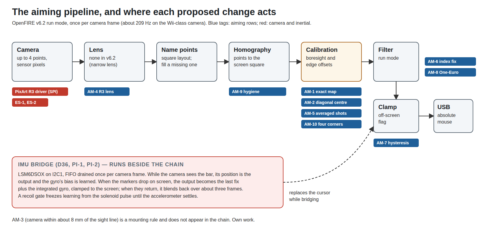
The Aiming Maths and Calibration dive re-derived the whole chain and simulated it (aim_maths.py); its Volume 7 §7.9 ranks the ten AM rows by value. This volume does not re-derive anything. It turns each row into work for the fork.
2.3 Calibration: AM-1, AM-2, AM-5, AM-10
These four change what OpenFIRE’s six-shot calibration stores. Together they are the highest-value group in the plan, because their errors appear at every distance and on every shot.
AM-1 — the exact offset map
- Source: Aiming Maths Vol 4 §4.3.
- Change: replace v6.2’s linear
map()of calibrated edge offsets with the exact inverse, as the ESP32 port’sMapCalibratedAxis()does. - Reason: v6.2 leaves an error of L(L+R)/res at the screen edges: about 4 mm with the bars 30 mm outside the picture and 22 mm at 80 mm, at every distance.
- Risk: low. The function is self-contained; the port’s version is LGPL like the file it replaces. Watch the sign conventions where the port’s axes differ.
- Test: host test against the simulation’s tables (Volume 5 §5.2); then on the bench, aim at printed edge targets after calibration and compare the cursor against the v6.2 build at two distances.
AM-2 — boresight from the diagonal intersection, unrotated
- Source: Aiming Maths Vol 4 §4.5–4.6.
- Change: store the centre shot as the intersection of the quadrilateral’s diagonals and drop the rotation by the calibration-time cant.
- Reason: v6.2’s mean-of-points centre is up to 18.5 mm off for a player who calibrated at an angle and moved; the cant rotation adds 3–12 mm with a tilted camera.
- Risk: low to medium. It changes stored calibration semantics: profiles calibrated under v6.2 are not valid under the fork and must be redone. The upgrade note (Volume 4 §4.7) says so.
- Test: host test with synthetic quadrilaterals; bench: calibrate from 30° off-axis, then shoot the centre target from straight on; the fork’s error should fall to the noise.
AM-5 — average each calibration shot over the held trigger
- Source: Aiming Maths Vol 4 §4.7.
- Change: while the trigger is held during a calibration step, average the positions over the hold, skipping the first frames after the pull; Prow Enhanced did this for its centre shot and OpenFIRE dropped it.
- Reason: one frame carries 0.56 mm of boresight noise in the simulation at 2.5 m; 70 frames take it to 0.07 mm, and the trigger jerk is excluded.
- Risk: low. The App’s calibration screen waits on the same stage messages; holding longer must not time anything out. The Hall trigger’s press point (CI-5, Volume 3) defines “held”.
- Test: twenty calibrations each with v6.2 and the fork at 2.5 m; compare the spread of the stored offsets.
AM-10 — optional four-corner calibration
- Source: Aiming Maths Vol 4 §4.9.
- Change: an optional mode fitting a full homography from four corner shots.
- Reason: absorbs emitter misplacement, 5–8 mm down to about 1.5 mm. Not needed with a well-mounted bar, which is why it is optional and last.
- Risk: medium. It is the only change in the plan that needs new per-profile data (eight numbers for each profile), the kind Volume 1 §1.5 warns about, so it is kept in a separate fork-owned file in the gun’s flash rather than added to the profile structure; and it needs a calibration sequence the stock App does not draw; it would run from the gun’s own pause menu or the bench tool. It is the change most likely to need an App fork to be usable by anyone but the builders.
- Test: deliberately misplace one emitter by 20 mm and compare edge errors with and without it.
2.4 Every frame: AM-6, AM-7, AM-8, AM-9
AM-6 — the run-mode index bug
- Source: Aiming Maths Vol 6 §6.3.
- Change: reset the shared averaging index when the run mode changes, as the ESP32 port does (its comment: “moveIndex can be 2 when coming from RunMode_Average2 … would then write past the end of the buffers (index 3)”).
- Reason: a write one past a three-element array and a frozen cursor, one time in three after a mode switch.
- Risk: none worth naming; a bug fix of a few lines.
- Test: the dive’s own reproduction, switching between a 2-frame and a 1-frame profile a dozen times while aiming, on v6.2 and then the fork.
AM-7 — off-screen hysteresis
- Source: Aiming Maths Vol 7 §7.8.
- Change: enter the off-screen state when the unclamped position passes the edge by a margin, leave it when it returns inside by the same margin; 1 % of the dimension to start.
- Reason: without it the flag flickers within about 2 mm of an edge, so a trigger pulled there reloads or fires at random.
- Risk: low. The flag drives button remapping (off-screen buttons, reload) and the Hold-to-Pause test, so every consumer of it must see the hysteretic flag, not a mix.
- Test: log the flag at the full frame rate while the gun is clamped 2 mm inside the edge; count transitions per minute, v6.2 against the fork.
AM-8 — a One-Euro run mode
- Source: Aiming Maths Vol 6 §6.11.
- Change: a fourth run mode filtering the cursor with a One-Euro filter, starting from f_min about 1 Hz and β about 0.007; Average stays the default until bench logs decide.
- Reason: fixed filters trade jitter against lag along one line; the One-Euro filter is steady at rest and quick on a flick.
- Risk: low for the code; the risk is tuning by feel. The run mode is stored per profile under the existing name
IrRunMode, so a new mode is only a new value, not a new field; but the stock App’s run-mode list knows only v6.2’s modes and would show a profile set to the new one as an unknown entry, and might write a different value back on commit. Selecting it from the gun’s pause menu, and checking what the App does with it, is part of the test. - Test: the dive’s bench method (§6.10): ten seconds clamped, then a scripted sweep, logging the cursor at full rate; jitter and lag against Average.
AM-9 — homography hygiene
- Source: Aiming Maths Vol 3 §3.9.
- Change: the ESP32 port’s cyclic corner order, guards against degenerate input, a 3 × 3 product, and a float literal where v6.2 promotes to double.
- Reason: no accuracy gain; it removes traps for later changes (AM-4 and AM-10 both project through the intermediate square) and about a quarter of the maths’ cycles.
- Risk: low, but it touches the hottest code in the firmware, so it goes in alone.
- Test: host test: identical outputs to v6.2 across the simulation’s poses within float tolerance, and the held-last-value behaviour on a degenerate frame.
2.5 AM-3: the change that is not firmware
AM-3 puts the camera within about 8 mm of the sight line, because parallax error is 0.6 times the offset over a 2.5 : 1 range of distances and calibration cannot remove it (Aiming Maths Vol 5). The ESP32 port has a dynamic parallax correction; the dive found it inactive or first-order and recommends the fork not switch it on. The printed MP7 tries two camera mounts (D43) and the bench parallax test decides. Nothing for the fork, unless that test fails.
2.6 The kit camera: a PAJ7025R3 driver on the Pico
- Source: Reference Electronics Vol 3 §3.11; decisions D18, D32; rows P-RE16, P-RE18, P-RE19.
- Change: bring the ESP32 port’s
PixArt_PAJ7025library into the fork beside the DFRobot/Wii driver, with a compile-time camera switch, SPI1 on GP12–GP15 (P-RE19), and the point format converted to what the position code expects. - Reason: D18 requires a camera that can be bought in quantity, and the only stock-OpenFIRE camera is a discontinued module or a salvaged Wii sensor. The PAJ7025R3 is in production; today only the ESP32 port reads it.
- Risk: the largest in this volume. The driver is small (the port’s copy, read on 19 October 2026, is 125 lines of header and 293 of source, LGPL, guarded by a
PAJ7025_CAMdefine), but it has never been published running on a Pico, and the port’s own Pico builds use upstream arduino-pico 6.3.0, while the fork is pinned to 4.5.4 (Volume 4 §4.5). The R3 also changes the units the rest of the pipeline works in: its 113° field puts about 1.15° in each pixel (Reference Electronics Vol 3), so every pixel-denominated threshold in the code (the point-sorting and missing-point logic among them) needs checking, not only the driver. - Test: first a bare read: product ID 0x7025 over SPI with the ADP3450’s logic analyser decoding the bus (Volume 5 §5.4); then four points from a bar at 2 m on the IR test view; then the full calibration and aim tests of 2.3 and 2.4 repeated on the R3.
Decision P-RE18 is still open: the alternative is to move the kit to the ESP32-S3 and use the port as it is. If the D25 dongle trial makes the kit wireless, that route wins on its own and this card moves to the ESP32 track (Volume 4 §4.3).
2.7 AM-4: the R3’s lens
- Source: Aiming Maths Vol 1 §1.7–1.9.
- Change: apply the ESP32 port’s two-term radial correction to each point before the homography, with coefficients from a bench sweep of real R3 samples.
- Reason: left alone the R3’s lens costs about 13 mm at 1 m on a 55-inch screen; corrected, about 0.2 mm in the simulation.
- Risk: medium. Coefficients from datasheet anchors are a guess; the decentred-lens term the model omits is unmeasured; one set may not serve every camera, which would make it a per-unit kit calibration.
- Test: the dive’s rotary-stage sweep (§1.9) on five or six samples; residuals after correction.
2.8 ES-1 and ES-2: frame subtraction and bar lock
- Source: Experimental Sensing Vol 2.
- Change (ES-1): a research build that writes the PAJ7025’s frame-subtraction register (bank 0,
0x28,Cmd_FrameSubtraction_On) and lets the bench watch what the sensor’s LED pins do. (ES-2): a control loop that treats the reported brightness of the four points as a phase detector and trims the sensor’s frame-period register so the camera’s exposure locks onto a free-running pulsed bar. - Reason: a pulsed bar at several times the steady current, seen only during the exposure, buys margin against room light; a lock needs no cable and no radio, works on the Pico, and lets any number of guns share one bar.
- Risk: both are research. The sensor’s behaviour with the register set is undocumented in the pages available. A lock loop that hunts would make the points flicker, which the off-screen and missing-point logic would read as the gun leaving the screen.
- Test: the dive’s Tests 1 to 3, on the ADP3450 with the pattern generator driving the bar.
These live on a research branch, never in a release, until Test 3 shows a real-room gain (Volume 4 §4.3).
2.9 The inertial sensor: D36, PI-1, PI-2
- Source: Positional and Inertial Vol 6; decisions D36, D38; rows PI-1, PI-2.
- Change: an LSM6DSOX driver on the shared peripheral bus I2C1 (GP18/GP19), FIFO on and polled once per camera frame, with no interrupt pin; then the dive’s state machine: LOCKED (learn gyro bias against the camera), BRIDGING (last fix plus integrated rate when the markers drop), OFF-SCREEN, REACQUIRE, and a recoil gate over all of them.
- Reason: the camera goes blind at the edges and when a hand covers it; a gyro bridges short gaps and gives a gesture reload with the camera blind.
- Risk: two concrete ones. Bus time: the OLED shares I2C1, and redrawing a full 128 × 64 SSD1306 frame is 1,024 bytes, about 23 ms at 400 kHz before protocol overhead (9 clocks a byte), during which the IMU cannot be read; the FIFO is what makes this harmless, so the FIFO depth and the drain rate must be checked against the longest OLED write. Recoil: the solenoid’s kick saturates and rings the accelerometer and, through a flexing board, the gyro; the recoil gate is not optional.
- Test: the dive’s bench tests, starting with Test 1 (whether the arduino-pico I2C driver drains a FIFO burst fast enough), then a logic-analyser capture of I2C1 with the OLED updating ammo during autofire.
2.10 Why these, and why not the others
The question here is not which part, but which source of change to trust. The criteria, in order: the change must be derived and simulated by a sibling dive (not copied because another fork did it); it must be testable on this lab’s bench before merge; and it must not need the stock App to understand it, or, if it does, it is deferred.
Table 1 — 2.10 Why these, and why not the others
| Source of change | Verdict | Reason |
|---|---|---|
| The sibling dives’ derived rows (AM, PI, ES) | Adopted as the plan | Each has a number behind it and a named bench test |
| The ESP32 port’s code, taken wholesale | Rejected | It fixes the map (AM-1) and the index (AM-6) but keeps v6.2’s mean and rotation; its filter is tuned hard on the points; its other changes come with its own camera and wireless layers (Aiming Maths Vol 4 §4.11). Individual functions are taken, with credit |
| Upstream’s next release | Not available | No push since v6.2 (19 April 2026); nothing published about v6.3 or v7 |
| Changes for their own sake (refactors, style) | Rejected | Every line changed in a hot file is a line to re-merge at each upstream release (Volume 4) |
The order inside the group follows the same logic as Volume 1 §1.8: calibration first (largest error, smallest risk), then the per-frame changes, then the camera and lens, which wait on hardware, and last the research branch.
2.11 What could not be verified
- All error figures are from the Aiming Maths simulation with an ideal camera; none has been measured.
- Whether the PixArt driver compiles and runs on the pinned arduino-pico 4.5.4 core; it was read, not built.
- The LSM6DSOX FIFO depth in the configuration Positional and Inertial proposes, against the OLED’s worst-case bus occupancy: the 23 ms figure is arithmetic from the frame size and bus rate, not a capture.
- The PAJ7025’s behaviour with
0x28set (Experimental Sensing’s open question).
Sources
- Aiming Maths and Calibration dive, Volumes 1, 3, 4, 5, 6 and 7, and its
04-templates/aim_maths.py— read 2026-10-19. - Reference Electronics dive, Volume 3 §3.10–3.11, Volume 2 — read 2026-10-19.
- Experimental Sensing dive, Volume 2 — read 2026-10-19.
- Positional and Inertial dive, Volume 6 — read 2026-10-19.
- Alessandro Satanassi,
OpenFIRE-Firmware-ESP32,lightgun/lib/PixArt_PAJ7025/(header and source, LGPL) andlightgun/platformio.ini(environmentsrpipico,rpipico2among them), snapshot downloaded 2026-10-19. - TeamOpenFIRE,
OpenFIRE-Firmwarev6.2,OpenFIREmain/OpenFIREcommon.cpp,libraries/OpenFIREPosition/— read 2026-10-19. - Category decision log, rows AM-1 to AM-10, P-RE16 to P-RE19, ES-1 to ES-6, PI-1 to PI-3, D18, D32, D36, D38 — read 2026-10-19.
Comments (0)