ZB 47 · Volume 3
How It Works: The Ratchet-Wheel Feed and the Magazine in the Stock
The ZB 47 as Zbrojovka Brno's 1947 manual describes it: six groups and twenty-four parts, a blowback bolt that never pushes a cartridge, a two-row ratchet wheel that swings each round up out of a magazine lying along the stock, the three-position takedown latch, the safeties, field stripping, upkeep, and what failed in trials
3.1 What the sources are
This volume is built on Zbrojovka Brno’s own manual, Samopal ZB 47, printed in 1947. The original is held by VHU, which photographed three of its spreads. The text used here is the 1997 Ofseta plus reprint, of which a complete scan is online.12 The manual is a sales brochure as well as an instruction book. Its section II describes the mechanism in about a page, its feed drawings are the only published drawings of the mechanism, and its section III gives the stripping sequence. Where this volume goes beyond the manual, it says so.
Three other sources add detail. VHU’s description of the ZB 46 explains the feed and the takedown latch in its own words.3 The 2010 palba.cz article was written from the manual and adds one dimension, the length of the feed lever’s reach.4 And the abstract of Brno’s 1937 British patent describes the feed principle (last section).5
No armourer’s manual, factory drawing set or spare-parts list was found. The ZB 47 never entered service, so none may ever have been written.
3.2 The six groups and twenty-four parts
The manual divides the gun into six groups for “simple handling and cleaning”. It then lists the parts of the fully stripped gun, numbered 1 to 24 and each drawn. The manual calls them “twenty-four parts that cannot be dismantled”.1
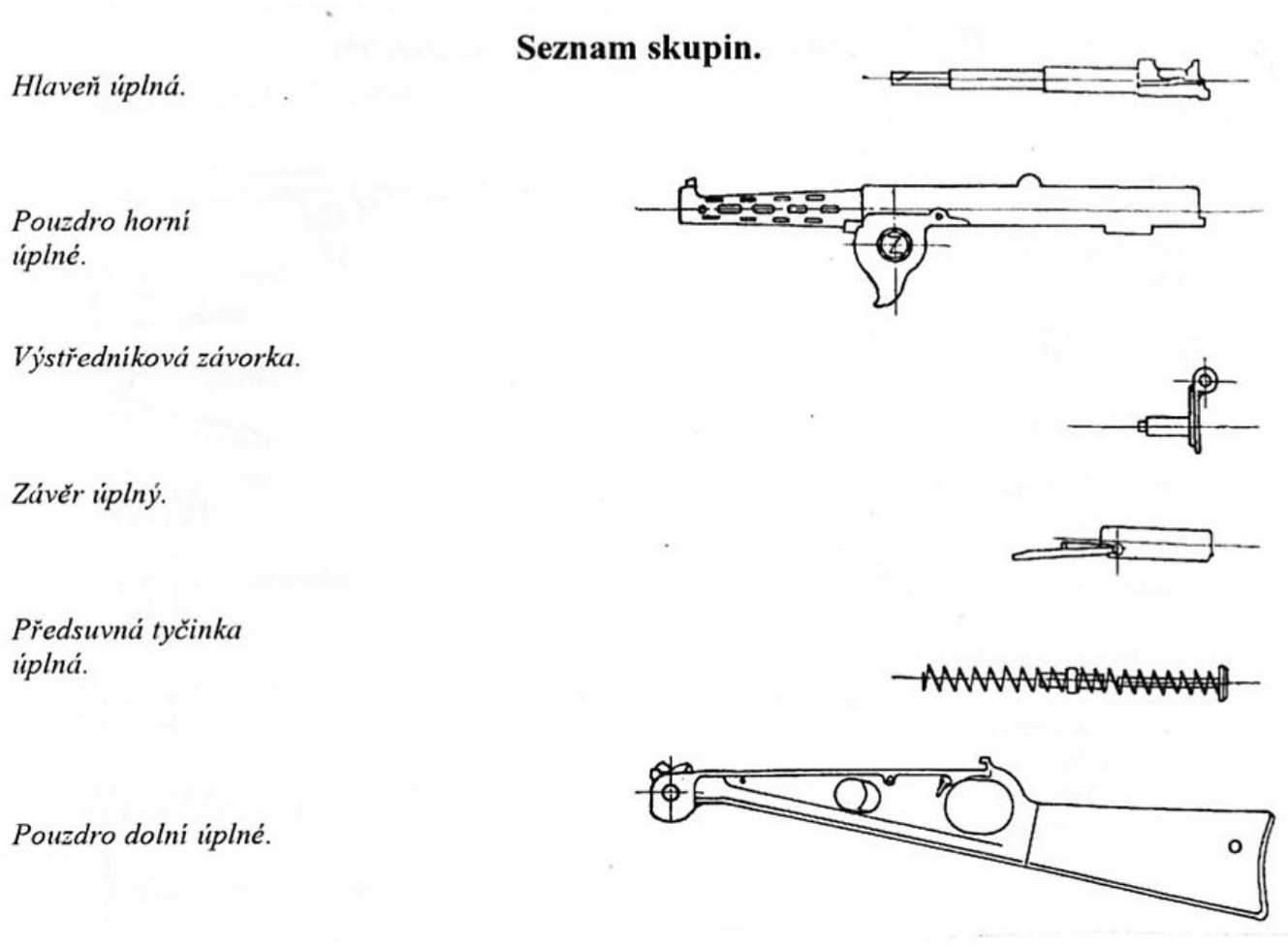
Table 1 — The six groups and twenty-four parts
| No. | Czech, as printed | English | Group |
|---|---|---|---|
| 1 | Hlaveň úplná | barrel, complete | barrel |
| 2 | Pouzdro horní úplné | upper housing, complete | upper housing |
| 3 | Závorník úplný | bolt, complete | bolt |
| 4 | Podávací páka | feed lever | bolt |
| 5 | Zpruha k podávací páce | feed-lever spring | bolt |
| 6 | Vytahovač | extractor | bolt |
| 7 | Opěrka vytahovače | extractor support | bolt |
| 8 | Zpruha k opěrce vytahovače | extractor-support spring | bolt |
| 9 | Předsuvná tyčinka úplná | return-spring rod, complete | return spring |
| 10 | Předsuvná zpruha úplná | return spring, complete | return spring |
| 11 | Pouzdro dolní úplné | lower housing, complete (the stock) | lower housing |
| 12 | Rohatkový kotouč | ratchet wheel | lower housing |
| 13 | Rohatková spojka | ratchet coupling | lower housing |
| 14 | Zpruha ke spojce | coupling spring | lower housing |
| 15 | Výstředníková závorka | eccentric latch | eccentric latch |
| 16 | Zádržka zásobníku | magazine catch | lower housing |
| 17 | Zpruha k zádržce zásobníku | magazine-catch spring | lower housing |
| 18 | Klička zádržky zásobníku | magazine-catch lever | lower housing |
| 19 | Spoušť úplná | trigger, complete | lower housing |
| 20 | Pojistka | safety | lower housing |
| 21 | Spouštěcí západka | trigger sear | lower housing |
| 22 | Vodicí tyčinka | guide rod | lower housing |
| 23 | Zpruha spouště | trigger spring | lower housing |
| 24 | Kolík spouště | trigger pin | lower housing |
Source: the manual, “Seznam součástek úplně rozložených”. The group column follows the manual’s text on what each housing holds; the assignment of the trigger and catch parts to the lower housing is inferred from it.1
Twenty-four parts is the field-level count. “Complete” (úplný) marks an assembly that the soldier did not take apart: the barrel, the bolt, the two housings, the spring and its rod. Production parts were counted differently. The manual says there were sixteen pressed parts, “many of them welded together into assemblies”, while the army’s July 1947 meeting counted 79 production parts in all (Volume 1).12
3.3 The two housings and the eccentric latch
The body of the gun is two sheet-metal pressings. The upper housing holds “the barrel with the ejector screw, the bolt with the feed lever, the extractor and the return spring”. The lower housing holds “the ratchet-wheel feeder, the trigger mechanism and the magazine”. The lower housing is also the stock, and the magazine “reaches to the rear end of the stock”.1
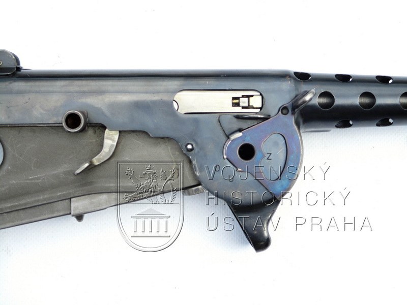
The two are held together by one part, the eccentric latch (výstředníková závorka). It does three jobs. It joins the housings. It is the hinge about which the upper housing tips open. And it is the axle of the feed wheel. In the manual’s words, it “also serves as the rotating shaft for the ratchet wheel of the feeder. About this shaft the upper housing tips into the open or closed position, according to whether it is drawn out of, or drawn into, the locking tooth of the lower housing by the eccentric latch.”1 VHU’s description of the ZB 46 explains how. The latch’s shaft is eccentric, so turning its lever on the right side moves the upper housing forward “far enough for a rib at the rear of the housing to leave a recess in the trigger-housing body”. The housing can then be tipped up.3
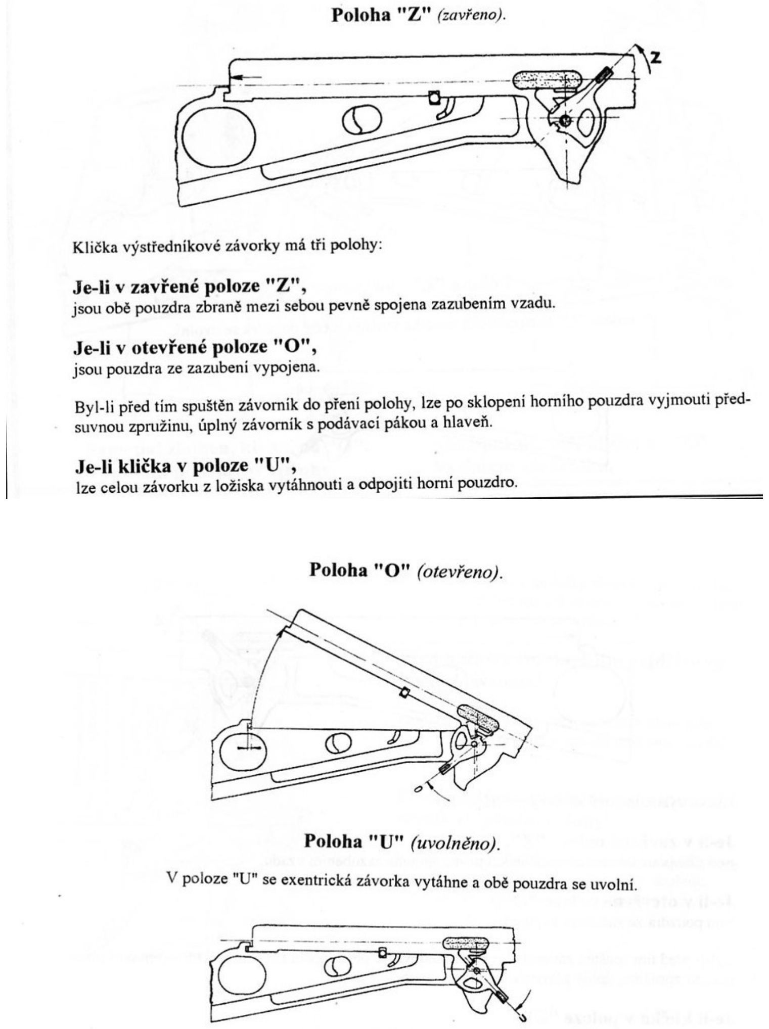
The lever has three positions, marked on the gun:1
- “Z” (zavřeno, closed). “Both housings of the gun are firmly joined together by teeth at the rear.”
- “O” (otevřeno, open). “The housings are disengaged from the teeth.” If the bolt was first let forward, the upper housing can be tipped up and the return spring, the bolt with its feed lever, and the barrel removed.
- “U” (uvolněno, released). “The whole latch can be drawn out of its bearing and the upper housing detached.”
The manual calls the joint “as safe and simple as possible”, and adds that “towards the shooter’s face the weapon is completely gas-tight”.1 The ZB 46’s oldest survivor has a two-armed latch lever joined to the eccentric shaft by a spring-loaded pin. The later guns have a one-armed lever made as a single part.3
3.4 The magazine
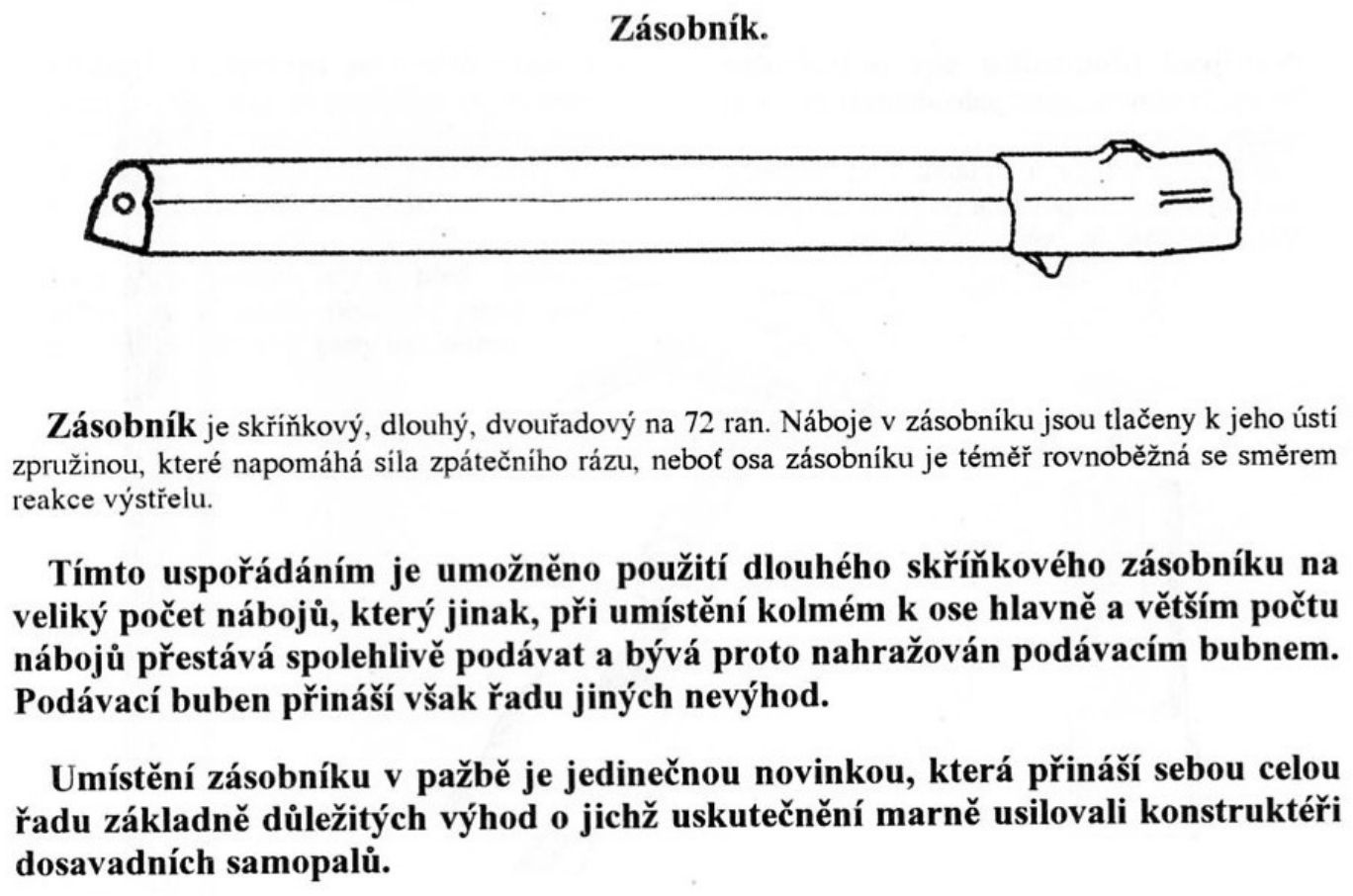
The magazine is “a box, long, two-column, of 72 rounds”. It weighs 360 g empty and 1,200 g full.1 It lies in a trough along the underside of the stock, with its mouth at the front, against the feed wheel below the chamber. Its long axis is “almost parallel to the axis of the barrel”.1 The rounds inside it therefore stand across the magazine, as in any box magazine. Because the magazine lies almost flat, they stand nearly upright, noses toward the bore line. This is how the manual’s feed drawings show them.
The manual makes two engineering arguments for the arrangement.
Recoil helps the spring. “The rounds in the magazine are pushed to its mouth by the spring, which is aided by the force of recoil, because the axis of the magazine is almost parallel to the direction of the reaction to the shot.”1 In a conventional magazine standing at right angles to the bore, recoil throws the column sideways against the magazine walls. Here it drives the column forward toward the feed, the direction the spring is already pushing.
A long magazine becomes possible. A box magazine of many rounds “otherwise, placed at right angles to the axis of the barrel and with a larger number of rounds, ceases to feed reliably and is therefore replaced by a feed drum. The feed drum, however, brings a series of other disadvantages.”1 The manual also claims that feeding is “absolutely reliable, because the rounds in the magazine are not set vibrating by the weapon”.1 That claim was not borne out by the troop trials, where the long magazine’s weakness was its tendency to bend (Volume 1).
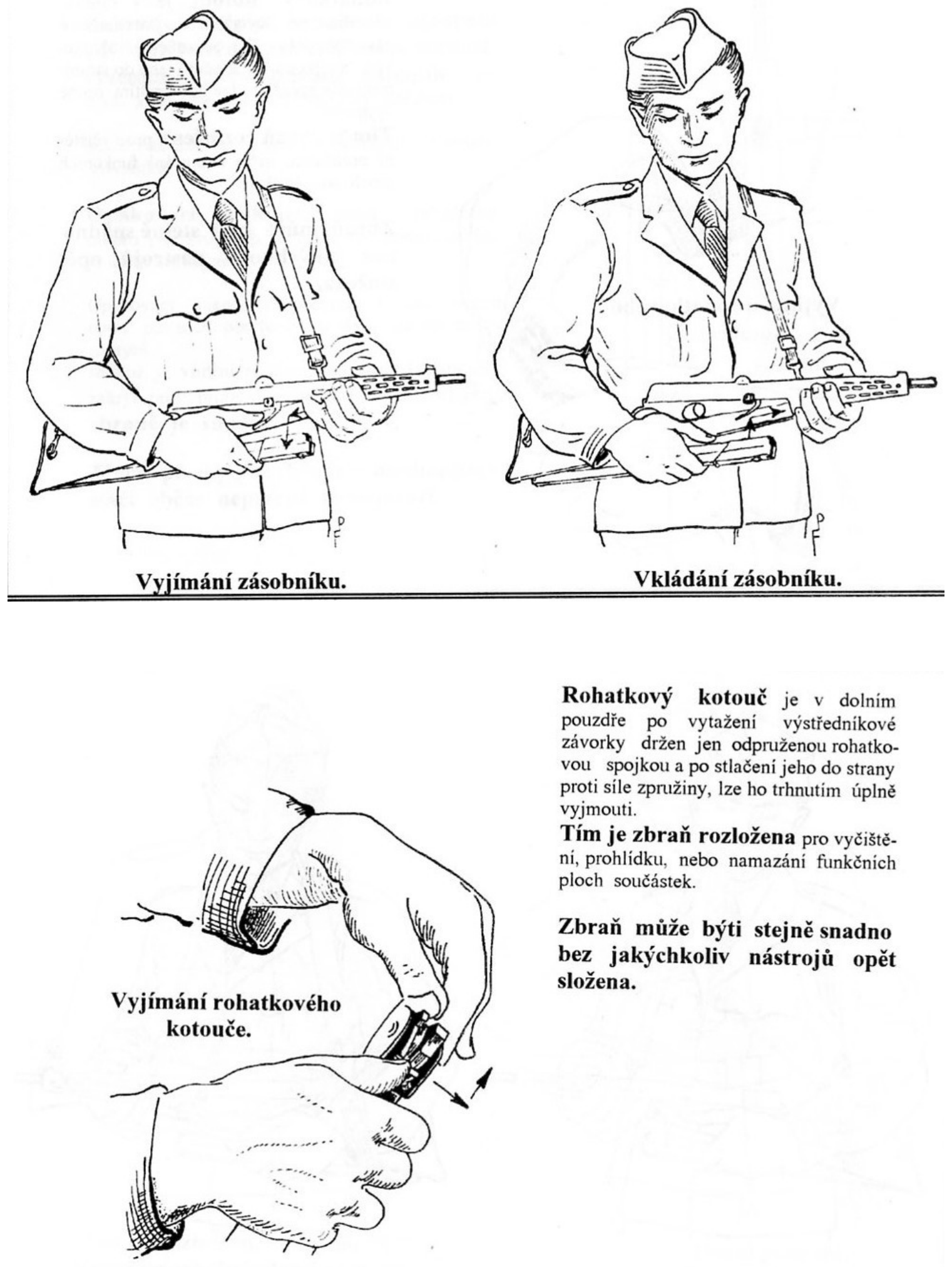
The gun is loaded by inserting “the rear end, tipping it into the trough and pushing it forward, whereby the magazine catch engages by itself”. To remove the magazine, the catch lever is pressed, and the magazine “slides somewhat to the rear and falls downward into the hand by itself”.1 Magazines were filled by hand or with “a simple loader” taking rounds in strips. The loader weighed 100 g. Spare magazines and the cleaning rod were carried in a canvas pouch on the belt.1
3.5 The ratchet-wheel feed
This is the part of the gun that has no parallel, and the manual’s description is short enough to give whole:
“The feeding device consists of a ratchet wheel turning on the shaft of the eccentric latch. The ratchet wheel has two rows of teeth. The feed lever engages the first row of teeth as the bolt moves forward, and turns the wheel by one pitch before each shot. The second row of teeth engages behind the base of the cartridge at the mouth of the magazine, and throws the cartridge along an arc into the chamber of the barrel. … The bolt comes into contact with the cartridge only at the moment of firing.”1
The parts involved are these:
- The ratchet wheel (part 12), on the latch shaft below the chamber. In the manual’s drawings it is a stubby four-lobed wheel. One row of teeth is driven by the feed lever. The other row carries the cartridges.
- The feed lever (part 4), pivoted on the bolt and kept in contact by its spring (part 5). According to palba.cz, written from the manual, the lever projects “about 30 mm” ahead of the bolt face.4 That reach is what lets a bolt still well back in the receiver turn a wheel under the chamber.
- The ratchet coupling (part 13) and its spring (part 14). The manual mentions the coupling only as the part that holds the wheel in the lower housing once the latch is out.1 Its role in the cycle is not described. A spring-loaded detent of this kind is the usual way to stop a ratchet wheel turning back or over-running. That is the likely function, but it is an inference.
VHU describes the same mechanism in the ZB 46 slightly differently. The feeder was turned through 90° by “a feed lever pivoted to the bolt”. The edge of the feeder pushed the top round out of the magazine lips “and guided it into a recess in the lower part of the barrel housing”. VHU adds that “the final phase of guiding it into the chamber was done by the face of the bolt”.3 This disagrees with the manual’s claim that the bolt touches the cartridge only at firing. The manual describes the production design of 1947 and VHU the ZB 46, so both may be right. In either case the wheel, not the bolt, does nearly all of the work of getting a round from the magazine to the chamber.
The four drawings in the manual show the sequence. They are reproduced here, followed by a schematic redrawn from them.
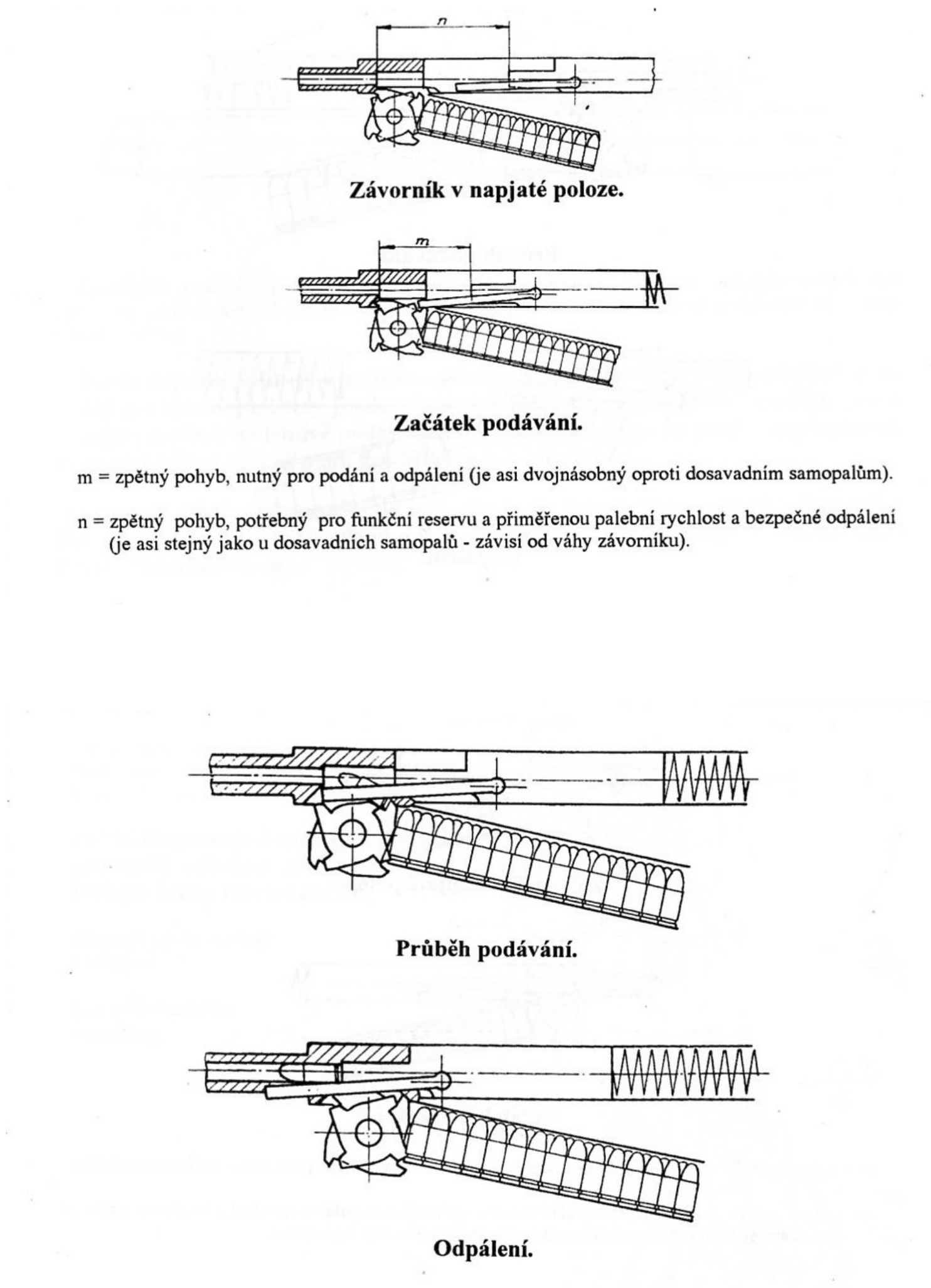
The manual’s legend explains why the gun is long behind the chamber. It defines two lengths of bolt travel:1
- m, “the rearward movement needed for feeding and firing”, is “about twice that of existing submachine guns”.
- n, “the rearward movement needed for a functional reserve, a suitable rate of fire and safe firing”, is “about the same as in existing submachine guns, depending on the weight of the bolt”.
The bolt has to run back far enough for the feed lever to clear the wheel and take the next tooth. That needs twice the usual stroke, and the receiver had to be long enough to contain it.
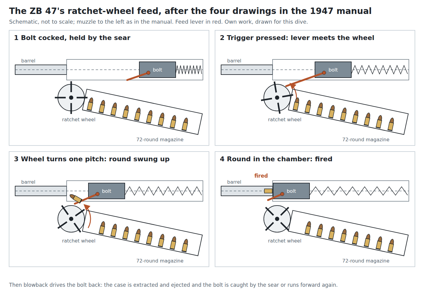
3.6 The cycle of operation
The manual calls the gun a blowback design “with a simple weight (dynamic) bolt”, “like most weapons of this category”.1 Nothing locks the breech. The bolt’s mass and the return spring hold the case in the chamber while pressure falls. It fires from an open bolt: the manual’s firing instructions begin with the bolt drawn back onto the sear. The MP 40 dive sets out the open-bolt blowback principle in full. What follows is the ZB 47’s own sequence, from the manual’s drawings and text.
- Cocked. With a full magazine in place, the bolt is drawn back by the cocking handle until it is held by the trigger sear (part 21). The return spring is compressed. The front round in the magazine stands at the mouth, against the wheel. The feed lever trails ahead of the bolt.1
- Trigger pressed. The sear releases the bolt, and the return spring drives it forward. As it moves, the feed lever engages a tooth of the wheel’s first row “and turns the wheel by one pitch before each shot”.1
- Feeding. As the wheel turns, a tooth of its second row, behind the base of the front round, “throws the cartridge along an arc into the chamber”. The round swings from upright in the magazine to lying in line with the bore. Meanwhile the magazine spring, helped on each shot by recoil, moves the column forward one place.1
- Fired. The bolt closes behind the chambered round and fires it. The manual says the bolt meets the cartridge “only at the moment of firing”.1 The manual does not say whether the bolt carries a fixed firing pin, and no drawing shows one. A fixed firing pin would be usual in a blowback open-bolt gun of the period.
- Recoil. Chamber pressure drives the case and bolt rearward. The extractor (part 6) holds the case on the bolt face, and the case strikes the ejector screw set in the barrel (the manual lists “the barrel with the ejector screw”) and leaves through the small ejection port.1 The bolt runs back its full stroke, with the feed lever riding back over the wheel’s teeth. That the lever rides over the teeth, rather than being lifted clear, is inferred from its spring; the manual does not describe the return stroke. If the trigger is still held, the bolt runs forward again and the cycle repeats. If not, the sear catches it.
The manual’s cyclic rate is 550 rounds a minute, and its ballistic table gives “0.11 s between shots”, which is the same thing.1 The long bolt stroke helps to keep the rate down. The ZB 46, demonstrated at about 1,200 rounds a minute, was the reason the army asked for a slower gun (Volume 1).3
3.7 Trigger, sear and the two safeties
The manual describes the controls in a few sentences.
Firing. “After the filled magazine has been inserted in the weapon, the bolt is drawn back into the firing notch of the sear, where the bolt can also be firmly locked. After the safety is released, fire can be opened by pressure on the trigger.”1 The safety (part 20) can therefore lock the bolt at the rear on the sear. The manual does not say how the safety is worked. No part of the manual describes a selector, and its parts list contains none (Volume 2).1
The automatic friction safety. The manual also describes a second safety, for the bolt when it is forward. This addresses the hazard the army had put first in July 1947: a bolt that a jolt drives back far enough to pick up a round and fire it.2
“If the bolt has been let forward on an empty chamber, it is held in its forward position by a friction safety, which works automatically as soon as the pressure of the finger on the trigger ceases. The essence of the friction safety is an inclined surface on the arm of the trigger, which, when the trigger blade is pressed, tips below the path of the bolt. On cocking, the bolt is again released automatically, because the resistance on the inclined friction surface is easily overcome.”1
In other words, when the trigger is at rest, an inclined face on the trigger arm sits in the bolt’s path and holds it forward by friction. Pressing the trigger drops it out of the way. Drawing the bolt back by hand simply overrides it. The palba.cz summary says the bolt “can be locked in both positions”, which matches the manual. It also says the gun “cannot be taken apart with the magazine inserted”, which the manual does not state in those words.4 The manual’s general claim is that correct handling is enforced “by mutual coupling or blocking of movements, which themselves enforce correct operation”.1 How the magazine and the latch are interlocked is not explained.
3.8 Keeping the dirt out
The manual claims that “particular attention” was paid to covering the working parts.1
- A small ejection port, “made possible by the special design of the bolt”.
- No slot for the cocking handle. “The cocking handle has no longitudinal opening for its movement, so coarse dirt cannot get into the weapon. The cocking handle moves in a narrow gap between the two housings, open only below and covered at the sides.”1
The VHU photographs are consistent with this. They show no long cocking slot along the receiver of the kind the Sten and the MP 40 have.2
3.9 Holding and carrying it
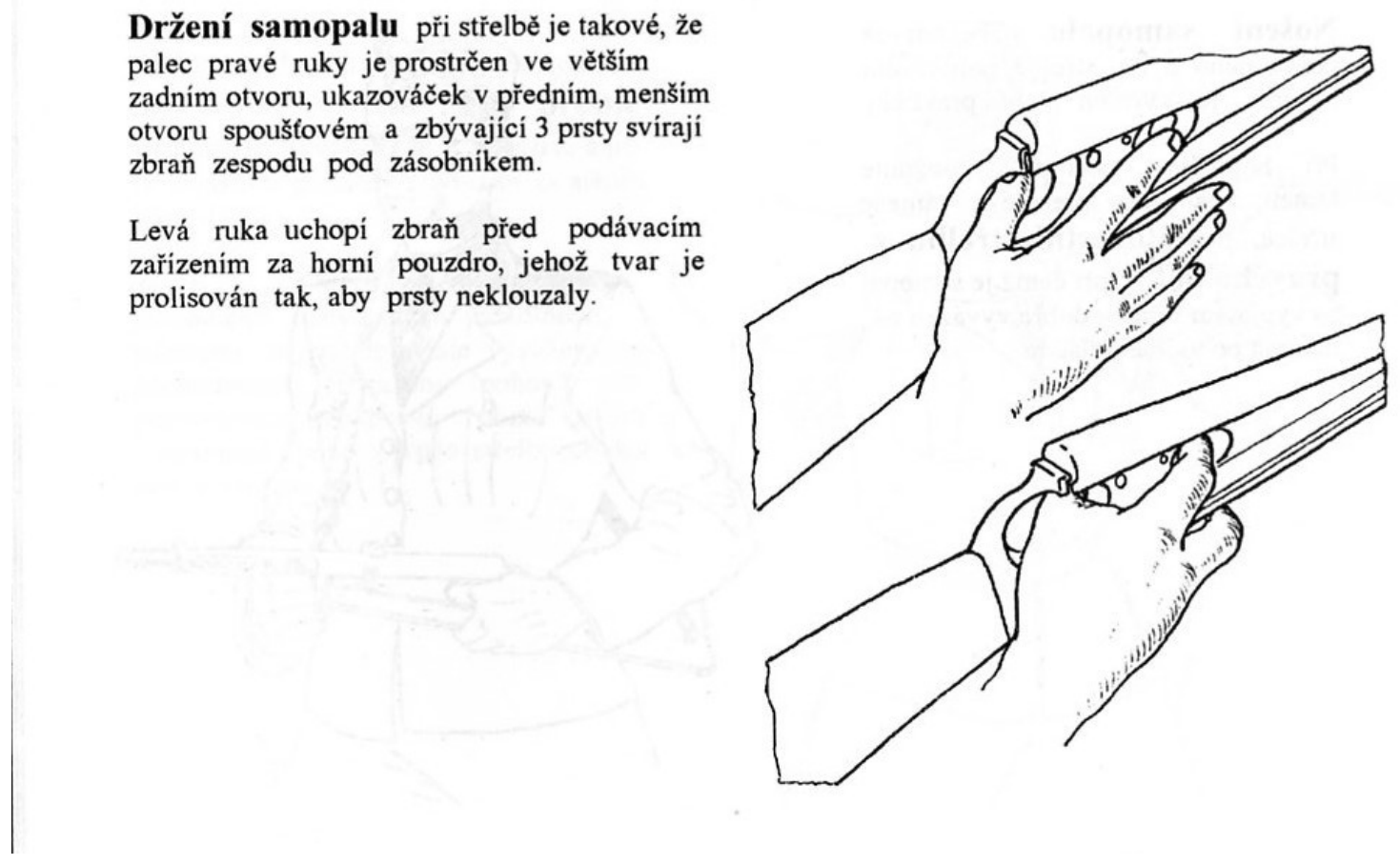
The manual’s description of the hold: “the thumb of the right hand is passed through the larger rear opening, the index finger into the front, smaller trigger opening, and the remaining three fingers grip the weapon from below, under the magazine. The left hand grasps the weapon ahead of the feeding device by the upper housing, whose shape is pressed so that the fingers do not slip.”1 The army’s first criticism of the ZB 46 in March 1946 had been the size of exactly these two openings, the trigger guard and the thumb hole (Volume 1).3
On the sling, the manual has the gun carried over the left shoulder, ready for firing from the right hip. The same sling length serves for shoulder fire, and for long marches the gun is slung muzzle down with the sling through the thumb hole. It stresses that the soldier is not chafed, “because his body is in contact only with smooth surfaces that have no projections or protruding magazine”.1
3.10 Field strip and detail strip
The manual’s section III gives the sequence. It is the only published procedure, and it is reproduced here as the manual gives it. Nothing has been added.1
- Remove the magazine first. “Before every dismantling, first remove the magazine!” Press the magazine-catch lever. The magazine slides back and drops into the hand.
- Let the bolt forward. “Before every dismantling, let the bolt forward into its front position!” (The friction safety then holds it.)
- Latch to “O”. The housings disengage. Tip the upper housing up (“samopal zlomen”, the gun broken open).
- Remove the return spring, then the bolt complete with its feed lever.
- Latch to “U”. Draw the eccentric latch out of its bearing, and the upper housing comes away. Remove the barrel from the upper housing.
- Remove the ratchet wheel. With the latch out, “the ratchet wheel is held in the lower housing only by the spring-loaded ratchet coupling, and after pressing it sideways against the force of the spring, it can be removed completely with a jerk”.
“With that the weapon is taken apart for cleaning, inspection or lubricating the working surfaces of the parts. The weapon can be put together again just as easily, without any tools whatever.”1 The manual gives no separate reassembly sequence. It is the reverse, and no step should be assumed beyond that.
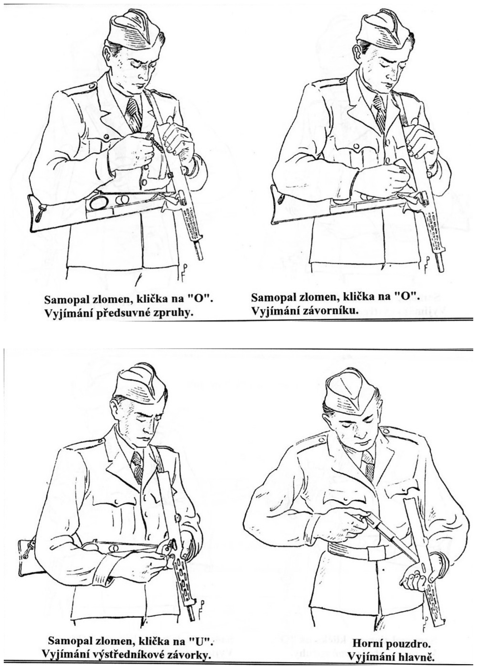
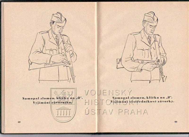
The manual goes no further than this. It does not cover removing the extractor, the trigger group, the magazine catch or the feed lever from the bolt. Parts 5 to 8 and 16 to 24 appear in the parts list but in no stripping instruction. No armourer’s procedure for them was found, and none is reconstructed here.
3.11 Maintenance
The manual’s maintenance instructions are brief. Because the mechanism is enclosed against coarse dirt, “cleaning the weapon is easy”, and “it is enough to oil the friction surfaces of the moving mechanisms slightly from time to time”.1 The six groups are the cleaning breakdown: the manual calls them the “list of groups of parts for simple handling and cleaning”. It gives no lubricants, intervals or inspection schedule, and no figures for parts wear or replacement.
Two things specific to this gun follow from the description and the trial record. The magazine and the trough it lies in must be kept straight, because the troop trials found that a dent in the thin lower pressing would stop the magazine going in.2 And the wheel and its coupling come out without tools, so they can be cleaned with everything else (step 6 above).
3.12 What failed, and what could be repaired
Every failure recorded comes from the army’s trials or from Brno’s own tests. None comes from service use, because there was none.
Table 2 — What failed, and what could be repaired
| Problem | Where recorded | What it means |
|---|---|---|
| Long magazine liable to deform | 1947–48 troop reports2 | A bent 72-round box will not feed or will not seat. |
| Thin housing walls dented by a blow, “especially where the magazine is housed”, stopping the magazine going in; “later confirmed in the trials” | troop reports2 | The stock is also the magazine well, so damage to the stock disables the gun. The palba.cz account notes that the lower housing was of thinner sheet than the upper.4 |
| Rate falling from 600 to 400 rounds a minute at −46 °C | Brno internal trials, reported July 19472 | Cold slows the gun but did not stop it; competing guns showed the same drop.6 |
| Short service life | Střelecká revue 2/2010, as recalled on palba.cz; attributed to substitute materials, not the design4 | Not seen in the original; no figure given. |
| Too heavy: 3.69 kg empty, 4.41 kg loaded, against a 3 kg ceiling | troop-trial assessment2 | Not a failure, but one of the reasons for rejection. |
On the other side of the ledger, Brno reported an 80,000-round endurance test and trials dirty with mud and sand before July 1947.2 The manual claims that “the feeding, firing and safety mechanisms show no stoppages in operation even after the endurance firing”.1 Neither Brno’s test report nor the army’s troop-trial reports were available, so the stoppage rates behind these statements are unknown.
On repair, little can be said. The manual names no armourer’s tools and no fitted parts. No spare-parts list was found. There is no source of parts for a gun of which perhaps 62 were made, all in public collections (Volume 2). Restoring a surviving example is a matter for the museums that hold them.
3.13 The 1937 patent and the gun
The feed principle is older than the gun. Brno’s British patent 502,782, with a Czechoslovak convention date of 20 August 1937, describes “a multi-sided drum … having a projection on each face to engage under the cartridges as they are fed to the drum in a path parallel to the bore … by a spring follower”. The projections lift “the end cartridge into the barrel … as the drum is rotated”. The breech-block “carries a toothed link which actuates teeth on a ratchet wheel mounted on the drum spindle, whereby the drum is rotated step-by-step at each reciprocation of the breech-block”. The breech end of the barrel has surfaces “to guide the cartridges smoothly into the barrel”.5
Every element of the ZB 47 feed is there: a column moving parallel to the bore under a spring; a wheel on a spindle that lifts the end round into the barrel; and a link on the breech-block that indexes the wheel through a ratchet once per cycle. The 1937 patent was aimed “particularly” at automatic pistols. In 1946 Brno put the column in the stock of a submachine gun, and in 1947 it patented the guide that brings the round into the chamber.3 The British abstract names no inventor, and the attribution of the 1937 patent to Václav Holek rests on VHU’s statement that patent CS 65 548 of 1937 protected “the principle of the feeding device, consisting of the ratchet wheel”.3
The ZB 47 is not the only weapon to turn cartridges through ninety degrees on their way to the chamber. Its magazine is not even the longest-lived. The P90 dive describes FN’s 50-round magazine, laid flat over the receiver, which turns each round through ninety degrees inside the magazine itself. The ZB 47 does the turning in the gun, with a wheel driven by the bolt, and that is where the parts count and the complication came from.
3.14 The manual’s own case for the gun
The manual closes with an argument from arithmetic. Holek’s gun, it says, “with 72 rounds in the magazine has such superiority in combat over other submachine guns of 30 to 36 rounds that on opening fire one ZB 47 balances two other submachine guns”. It goes on: “When firing 1,000 rounds, 2 ZB 47 balance three other submachine guns.” Two ZB 47 gunners would fire 1,000 rounds in about 1.5 minutes, a task that needs three men with other guns.1 It proposes judging a gun by its weight or price divided by the rounds in its magazine. On that measure, a loaded ZB 47 wins “even if the other submachine gun alone, for half the number of rounds in the magazine, were 1 kg lighter”. The manual ends with an analogy: “the same holds as for a motor vehicle, where the cheapest can be the most expensive”.1
Other claims in the manual are those of a brochure. It credits the 9 × 19 mm round with “lethal effect” at 750 m. It gives 100 m accuracy of 10 rounds out of 11 in a 20 cm square, single shots, and 30 rounds in a 30 cm square in short bursts.1 These are the maker’s figures for its own gun. No independent test of them was found. The army’s own dispersion figures, from Popovice in 1948, are in Volume 1.
The army did not accept the argument. It wanted few parts, low weight and toughness, and it weighed those above firepower per magazine.2 The design idea itself was sound. Its execution, in 79 production parts and thin pressings, was not what the army wanted.
3.15 What could not be verified
- How the wheel’s direction of rotation and the cartridge’s arc relate in detail. The manual’s drawings are small and schematic, and the own-work schematic follows them without adding detail.
- The ratchet coupling’s role in the cycle. It is described only as what holds the wheel in place.
- Whether the bolt finishes chambering the round. The manual says the bolt meets the round only at firing. VHU says the bolt face completed the chambering in the ZB 46.
- The firing pin: fixed or separate. No source states it.
- How the safety is operated, and how the magazine–takedown interlock that palba.cz reports works.
- Any armourer’s procedure below the field strip, and any parts list with part numbers.
- The patents’ drawings and inventors. Only abstracts were read.
References
Footnotes
-
Zbrojovka Brno, národní podnik, Samopal ZB 47 (1947); reprinted as Samopal ZB 47 Holek. Odborný český překlad původního návodu k obsluze včetně vyobrazení (Ofseta plus, 1997, 56 pp.). Scan of the reprint at http://sa58kinggun.jansladky.cz/Podklady/Holek1.pdf (online since at least 2015 per the Wayback Machine; fetched 2026-10-19). Sections cited: B (the new gun), I (groups and parts), II (description, handling, firing), III (dismantling, cleaning), V and VI (technical data), VII (conclusion). Quotations translated for this dive; the Czech is in
02-inputs/research-manual.md. ↩ ↩2 ↩3 ↩4 ↩5 ↩6 ↩7 ↩8 ↩9 ↩10 ↩11 ↩12 ↩13 ↩14 ↩15 ↩16 ↩17 ↩18 ↩19 ↩20 ↩21 ↩22 ↩23 ↩24 ↩25 ↩26 ↩27 ↩28 ↩29 ↩30 ↩31 ↩32 ↩33 ↩34 ↩35 ↩36 ↩37 ↩38 ↩39 ↩40 -
Jan Skramoušský, “Samopal ZB 47”, VHU Praha, https://www.vhu.cz/samopal-zb-47/ (published 2018-11-27; accessed 2026-10-19). Photographs of the original manual and of the infantry gun; the trial record. ↩ ↩2 ↩3 ↩4 ↩5 ↩6 ↩7 ↩8 ↩9 ↩10 ↩11
-
“Čs. samopal ZB 46”, VHU Praha, exhibit page, https://www.vhu.cz/exhibit/cs-samopal-zb-46/ (accessed 2026-10-19). Feed and takedown latch of the ZB 46; the three patents. ↩ ↩2 ↩3 ↩4 ↩5 ↩6 ↩7 ↩8
-
“sa58”, “Samopal ZB 47”, palba.cz, http://www.palba.cz/viewtopic.php?t=3998 (2010-04-05, with replies; accessed 2026-10-19). The feed lever’s 30 mm reach; the interlock; Střelecká revue 2/2010 on service life. ↩ ↩2 ↩3 ↩4 ↩5
-
GB 502,782, “Cartridge feed mechanism for automatic firearms”, Československá zbrojovka a.s., Brno; convention date 20 August 1937. Abstract via https://patents.google.com/patent/GB502782A/en (read 2026-10-19). ↩ ↩2
-
Jan Skramoušský, “Samopal ČZ 247”, VHU Praha, https://www.vhu.cz/samopal-cz-247/ (published 2018-10-29; accessed 2026-10-19). ↩
Comments (0)