STEN Gun · Volume 4
Engineering & Reference Data — Drawings, Dimensions, Materials
Original UK MoS drawings, US TM reproductions, community-reverse-engineered dim sheets, per-part engineering data
4.1 Contents
(Generated by build/inject_toc.py at build time. Section headers below are the source of truth.)
This is the load-bearing engineering volume — the one that Vols 6 (Build Path B parts kit) and 7 (Build Path C from scratch) both cite. Where Vol 2 told the story of how the STEN was made, this volume documents the engineering archive that makes a modern build possible: where the original drawings live, what they say, how to read them, and how community-reverse-engineered modern work supplements them. The STEN is the cleanest engineering archive in the Firearms hub — unlike the Mauser C96 (no public factory drawings exist) or the E-11 (community-consensus prop dim sheets only), the STEN has a rich public-domain primary source archive plus a deep modern community of reverse-engineered drawings and dimensioned reproductions.
The volume is organized in three layers, working outward from the most-authoritative to the most-accessible:
- The archive itself (§ 4.1) — what exists, where it physically lives, what its copyright posture is, and how to access it.
- Cardinal dimensions and specifications (§ 4.2) — the headline numbers a builder needs at a glance for a Mk II build.
- Per-part engineering (§§ 4.3–4.10) — the receiver tube, bolt + firing pin, trigger group housing, barrel + chamber, magazine, stock, materials, and surface treatments — each one part-by-part, with the engineering rationale tied back to the 1941 design brief from Vol 2.
Vol 7 takes the per-part engineering and turns it into an op sequence in the lab. Vol 6 takes the same engineering and turns it into a parts-kit assembly procedure. Vol 8 takes the same engineering and goes one level deeper on the parts-level mechanics for the user who wants to understand why each part is the way it is. This volume is upstream of all three.
4.2 The engineering archive — what exists and where
The STEN engineering archive falls into four buckets by source and copyright status. A modern builder pulls from all four; the deep-dive author cites all four.
4.2.1 UK Ministry of Supply original drawings
The canonical primary source is the UK Ministry of Supply (MoS) drawings package for Carbine, Machine, 9 mm STEN, prepared at RSAF Enfield and disseminated to the production thicket (BSA, Fazakerley, Theale, Lines Brothers, Long Branch, Lithgow) during the war. The drawing set consists of approximately 80–120 individual sheets per Mark (the exact count varies — the Mk II set is the most-complete; the Mk III set is smaller because the receiver is a single-piece stamping rather than a parts-tree of subassemblies; the Mk V set adds the wooden-furniture and Lee-Enfield-sight drawings on top of the Mk II base).
Where they physically live:
- The National Archives Kew (Richmond, London). A search of its catalogue (Discovery, 2026-10-11) finds no catalogued STEN drawing set. What Kew catalogues is the wartime paper trail around the drawings: Ministry of Supply contract and design files in AVIA 22, RSAF Enfield / Ordnance Board files in WO 185, and trials reports in WO 291. Some of these files are likely to contain drawings, but the catalogue does not say which. The most promising references are listed in § 4.1.5.
- The Royal Armouries Leeds holds the archives of the Royal Small Arms Factory (Enfield) and the MOD Pattern Room, which is where any surviving RSAF drawing-office material should be. Only a small part of that archive is searchable online, so the holding has to be confirmed by asking the archivist (§ 4.1.5).
- The Imperial War Museum. Its online collection lists STEN objects (for example FIR 6260.1, a Mk II by ROF Fazakerley, and FIR 6265.1, a Lines Brothers Mk III) but no STEN drawings were found in it (2026-10-11). An earlier version of this volume said IWM Duxford holds drawings; that is unconfirmed.
- Various enthusiast scans are circulated online via the small-arms-history and reenactor communities; these are derivative works of variable quality. The most-cited modern compilation is the one by Frank Iannamico (the American Rifleman / Small Arms Review author who has serialized STEN engineering content over decades).
Copyright status: UK Crown Copyright on unpublished government material runs for 125 years from creation, or 50 years from first publication, whichever is shorter. The 1941–1945 drawings are technically still under Crown Copyright until 2066–2070 if they were never published. However, the practical posture is governed by the UK Open Government Licence (OGL) — Crown Copyright material is freely usable for any purpose under OGL provided attribution is given to ”© Crown copyright, used under the Open Government Licence v3.0.” Modern reproductions in the small-arms-history literature (Iannamico, Skennerton) cite the drawings under fair dealing for criticism, review, and news-reporting purposes; the more-cautious posture for a hobbyist publication like this deep dive is to cite the drawings by SA-prefix reference number and source institution rather than reproducing them inline. Vol 4 cites; Vol 7 builds from the cited drawings.
4.2.2 US Technical Manual reproductions
The second primary source is US government material that described the STEN during and after WWII: wartime OSS supply files and Cold War US Army foreign-weapons studies. It is US federal government work product and public domain by statute (17 USC § 105). All three items below are in this dive’s Reference Library.
- US Army Special Forces Foreign Weapons Handbook (US Army John F. Kennedy Center for Special Warfare, Fort Bragg, 1 January 1967; DTIC AD0867982, approved for public release). A 385-page teaching handbook on foreign small arms with an entry on the 9 mm Mark V STEN, including notes on the Mk II and on parts mixed between Marks.
- FSTC 381-5012 — Typical Foreign Unconventional Warfare Weapons (U), US Army Foreign Science and Technology Center (undated, post-1964; on Wikimedia Commons). Its small-arms section describes and photographs two Viet Cong Sten-type submachine guns built around Mk II pattern parts, the clandestine-fabrication afterlife of the design. The title page also prints the number as 381-4012.
- OSS file, 1942 — Military Equipment and Supplies for Guerrilla Operations / Production of STEN Submachine Guns and Ammunition in the U.S. (CIA CREST release CIA-RDP13X00001R000100300008-3). Wartime correspondence on having STENs and their ammunition made in the United States for guerrilla supply. Production history rather than engineering data.
Correction. Earlier versions of this deep dive cited TM-E 9-1985-3 as a 1944 Catalog of Enemy Ordnance Material with STEN content. That citation was wrong. TM 9-1985-3 is German Explosive Ordnance (Projectiles and Projectile Fuzes), 1953, and has nothing on the STEN. The STEN, a British weapon, would not appear in a US catalogue of enemy ordnance in any case.
Copyright status: Public domain for the US-government-authored material. Scans of the original printed manuals from the National Archives, the National Security Archive, or the Wikimedia Commons PD-USGov bucket are all freely usable.
4.2.3 Modern community-reverse-engineered drawings
The modern community archive is unusually deep for the STEN because the gun has been a parts-kit-builder and clandestine-fabrication subject for decades. The most-cited modern sources:
- Professor Parabellum’s Practical Scrap Metal Small Arms series — Volume III: The DIY STEN Gun (distributed in Wikimedia Commons as a PD/CC-BY-1.0 PDF) is a dedicated dimensioned-drawing-and-op-sequence treatment of the STEN. Vol III is the STEN-specific volume; Vol I covers other garage-fabrication small arms. The Professor Parabellum drawings are a complete reverse-engineered MoS-equivalent set, with dimensions in both metric and imperial, suitable for a hobbyist lab build. (Note: Vols 1 and 2 of this deep dive originally cited “Vol I” as the STEN treatment; the correct reference is Vol III. Errata captured in the volume-source notes.)
- Apex Gun Parts technical sheets — Apex publishes per-parts-kit technical documentation for the STEN kits they sell; the documentation includes 922(r) parts-count arithmetic, receiver-tube compatibility, and assembly notes. Vendor-copyrighted; cited in Vol 6 by reference.
- The Cabin Press fabrication manuals of the 1970s–80s — a body of US-enthusiast fabrication literature on improvised firearms; not the most-respectable source but historically important. Variously copyrighted; reference-only.
- The forum archives at Subguns.com, AR15.com STEN forum, and the Sturmgewehr.com STEN board — decades of community build-thread documentation, parts-vendor reviews, and per-step photo essays. Useful for the Vol 7 author who wants to see how other lab builders solved each per-part fabrication problem. Variously copyrighted; reference-only.
4.2.4 The collector-reference literature
The scholarly collector literature does not produce engineering drawings per se but cites and contextualizes them. The standard works:
- Skennerton, Ian. The Sten Machine Carbine. The standard collector reference. Cites the UK MoS drawings by SA-prefix number, gives dimensioned summaries, and catalogues per-Mk variation. Indispensable for a builder researching pre-acquisition. (Australian-published; Skennerton’s Small Arms Identification Series is the parent line.)
- Hogg, Ian V., and John Weeks. Military Small Arms of the 20th Century. General reference; per-Mk dimensioned summaries.
- Iannamico, Frank. The STEN Submachine Gun. (Moose Lake Publishing, multiple editions.) The Iannamico work is a parallel-canon collector reference with deeper engineering detail than Skennerton on some Marks; cites the UK MoS drawings extensively.
- Bishop, Chris. The Encyclopedia of Weapons of World War II. General reference; production-volume facts.
Copyright status: Commercial publications; cited by author/title/page but not reproduced.
4.2.5 Ordering copies from the archives
The printed manuals, parts lists and US handbooks named in this section are already in this dive’s Reference Library. The original drawings are not online anywhere. Getting them means ordering copies from the institutions below, or visiting. Prices and terms were checked on 2026-10-11 and change; confirm them when ordering.
The National Archives, Kew — the only one of the three with a published price list and an online order route.
The files most likely to hold STEN drawings or dimensioned design material:
Table 1 — The files most likely to hold STEN drawings or dimensioned design material
| Reference | Catalogue title | Dates |
|---|---|---|
| AVIA 22/1616 | Sten gun improvements. Brig. G. Temple, Major R.V. Shepherd and H.J. Turpin | 1941–1947 |
| WO 185/144 | Re-designated Sten Mk II (S) F5: Silent Weapon | 1941–45 |
| AVIA 22/2800 | Carbine, machine, Sten, 9 mm, Mk. II, sleeve, barrel. C.J. Neumann, London | 1942–1948 |
| AVIA 22/1565 | Manufacture of rifled barrels for sten guns. Accles & Pollock Ltd and W. W. Hackett | 1941–1945 |
| AVIA 22/1371 | Singer Manufacturing Co. Ltd: assisted scheme for production of Sten Machine Carbine Gun | 1941–1947 |
| AVIA 22/1524 | Sten gun. Sterling Armament Co. Ltd. | 1942–1943 |
| CAB 122/227 | Sten Gun programme | 1942 |
| DSIR 27/41/ID4 | Time-displacement relations of the Sten gun. By A.G. Tarrant | Nov. 1941 |
| WO 291/476 | Comparison of rifle, bren and sten guns | 1944 |
| WO 291/1664 | Protection of Sten, Owen and Bren magazines against fouling under jungle conditions | 1952 |
| ADM 204/1527 | Infra-red equipment for use with Sten carbine | 1944 |
| AIR 66/333 | Method of packing carbine machine sten MKII with filled magazine and accessories… | 1960 |
AVIA 22/1616 (the designers’ own improvement file) and WO 185/144 (the Mk II (S)) are the best first orders. The rest are contract, production and trials files, useful for history and only possibly for drawings. All are open records.
How to order a copy without visiting:
- Find the file in Discovery by its reference and use “Order a copy” at the bottom of the entry.
- Pay the page check: £9.92. Staff look through the file, count the pages and send a costed quote. It normally takes up to 10 working days. The quote is valid for six weeks, and the fee is not refunded once work starts, including when the file turns out not to contain what was hoped. Kew warns that page checks on speculative requests may fail, and staff cannot research the contents, so a request is best framed as “copy the whole file” or “copy all drawings in the file”.
- Accept the quote and pay per copy:
Table 2 — 3. Accept the quote and pay per copy
| Copy type | Up to A3 | Larger than A3 |
|---|---|---|
| Digital | £1.52 per copy | £11.95 per copy |
| Colour paper | £7.40 per copy | £17.71 per copy |
Postage on paper copies is extra. A folded drawing larger than A3 counts at the higher rate, which is where the cost of a drawing-heavy file adds up.
Format: digital or paper, but digital is not PDF. Digital copies are supplied as 300 dpi JPEG images, one per page, downloaded from Kew’s website within three months of the email notice. Paper copies are printed in the A3 to A2 range, with no enlargement, and posted or held at the reading room for 28 days. Copying normally takes up to 14 working days after the quote is accepted; Kew puts the whole process at roughly 29 working days.
Visiting. Kew lends original documents to readers with a free reader’s ticket. Photographing documents with your own camera or phone is allowed for personal use and research, without flash or tripods; camera stands are limited, so book ahead. For a large file, one visit costs nothing in copying fees. Independent record agents will also photograph files at Kew for a fee.
The Royal Armouries, Leeds — the RSAF Enfield and MOD Pattern Room archives.
- Contact: Archivist, Royal Armouries Museum, Armouries Drive, Leeds LS10 1LT. Email [email protected].
- Access is by appointment only, Tuesday to Friday, 10:00–13:00 and 13:30–16:30.
- Ordering: the Royal Armouries runs a record copying service but publishes no prices and no formats. The first email should ask:
- whether the archive holds STEN drawings (RSAF Enfield drawing office or the Pattern Room);
- what the references are;
- the cost per sheet;
- whether scans are supplied digitally, in what format and resolution, or as paper only.
- Publishing: reproduction rights for publication go through the separate Royal Armouries image-licensing service, not the copying service.
The Imperial War Museum. No STEN drawings were found in IWM’s online collection. A collections enquiry would settle whether any are held in uncatalogued document collections. IWM publishes no current copying price for documents.
Re-use. Before scans are put in a public library, check the re-use terms printed on the copy order. Published War Office material from 1942–44 is out of Crown copyright. Unpublished drawings are a separate question (see the copyright note in § 4.1.1).
4.3 Cardinal dimensions and specifications — Mk II reference
The Mk II is the canonical build target (§ 3.2). The headline specifications a builder needs at a glance, drawn from the UK MoS drawings via Skennerton and Iannamico cross-referenced with the Professor Parabellum modern reverse-engineered set:
Table 3 — The Mk II is the canonical build target (§ 3.2). The headline specifications a builder needs at a glance, drawn from the UK MoS drawings via Skennerton and Iannamico cross-referenced with the Professor Parabellum modern reverse-engineered set
| Specification | Mk II value | Notes |
|---|---|---|
| Caliber | 9×19 mm Parabellum | Factory; SAAMI modern chamber drops in |
| Action | Open-bolt, blowback, select-fire (semi/full-auto) — for original WWII production; closed-bolt semi-auto-only required for new US semi-auto builds, because ATF Rul. 83-5 (1983) classifies an open-bolt semi-auto STEN as a machine gun (see § 4.4) | |
| Cyclic rate (full-auto) | ~550 rpm | Open-bolt; varies with magazine spring strength + bolt mass + ammo charge |
| Overall length, stock attached | 762 mm (30.0″) | With skeleton T-stock |
| Overall length, stock detached | 553 mm (21.8″) | Mk II stocks are detachable |
| Barrel length | 197 mm (7.75″) | Factory; constitutes a federal SBR for US semi-auto builds unless extended to ≥16″ (see Vol 10) |
| Weight, empty, with stock | 3.18 kg (7.0 lb) | Magazine empty; varies slightly by factory |
| Weight, loaded (32-rd mag) | ~3.65 kg (8.05 lb) | |
| Receiver tube outside diameter | ~38 mm (1.50″) | Rolled-and-welded sheet steel, ~2.0–2.5 mm wall |
| Receiver tube length | ~533 mm (~21.0″) | The full tube from buttplate-cap to muzzle-bushing |
| Bolt diameter (sliding fit) | ~32 mm (~1.26″) | Slides inside the receiver tube; clearance ~2–3 mm radial |
| Bolt length | ~210 mm (8.27″) | Approximate; varies slightly by factory |
| Bolt mass | ~590 g (~1.3 lb) | The mass that drives the open-bolt blowback timing |
| Recoil spring free length | ~280 mm (~11″) | Compresses to ~145 mm at bolt-rearward |
| Magazine capacity | 32 rounds | Single-feed, Lanchester-derived (MP 28 ancestry) |
| Trigger group housing material | Stamped sheet steel (Mk II UK production) or cast aluminum (Long Branch Mk II, mid-war + late UK Mk II) | |
| Sights | Fixed front blade + flip aperture rear, 100 yd | Mk V replaces with Lee-Enfield No 4 |
| Stock | Skeleton T-frame, welded steel rod, ~9.5 mm diameter | Some Mk II variants use a wire-loop instead |
All values above are Mk II canonical; per-factory and per-Mk variation are documented in §§ 4.3–4.8 with specific delta-from-Mk-II notes where they matter for a build. Builders preparing for shop work should verify any single critical dimension against a UK MoS drawing or a confirmed-good Professor Parabellum Vol III page before cutting metal — the Mk II benefits from a deep archive and tolerates substantial per-factory variation, so a +/- 0.5 mm at the dim-table level is fine for orientation but a tight-tolerance critical interface (bolt-to-tube clearance, chamber-to-bolt-face) is worth a source-document check.
4.4 The receiver tube — engineering deep-dive
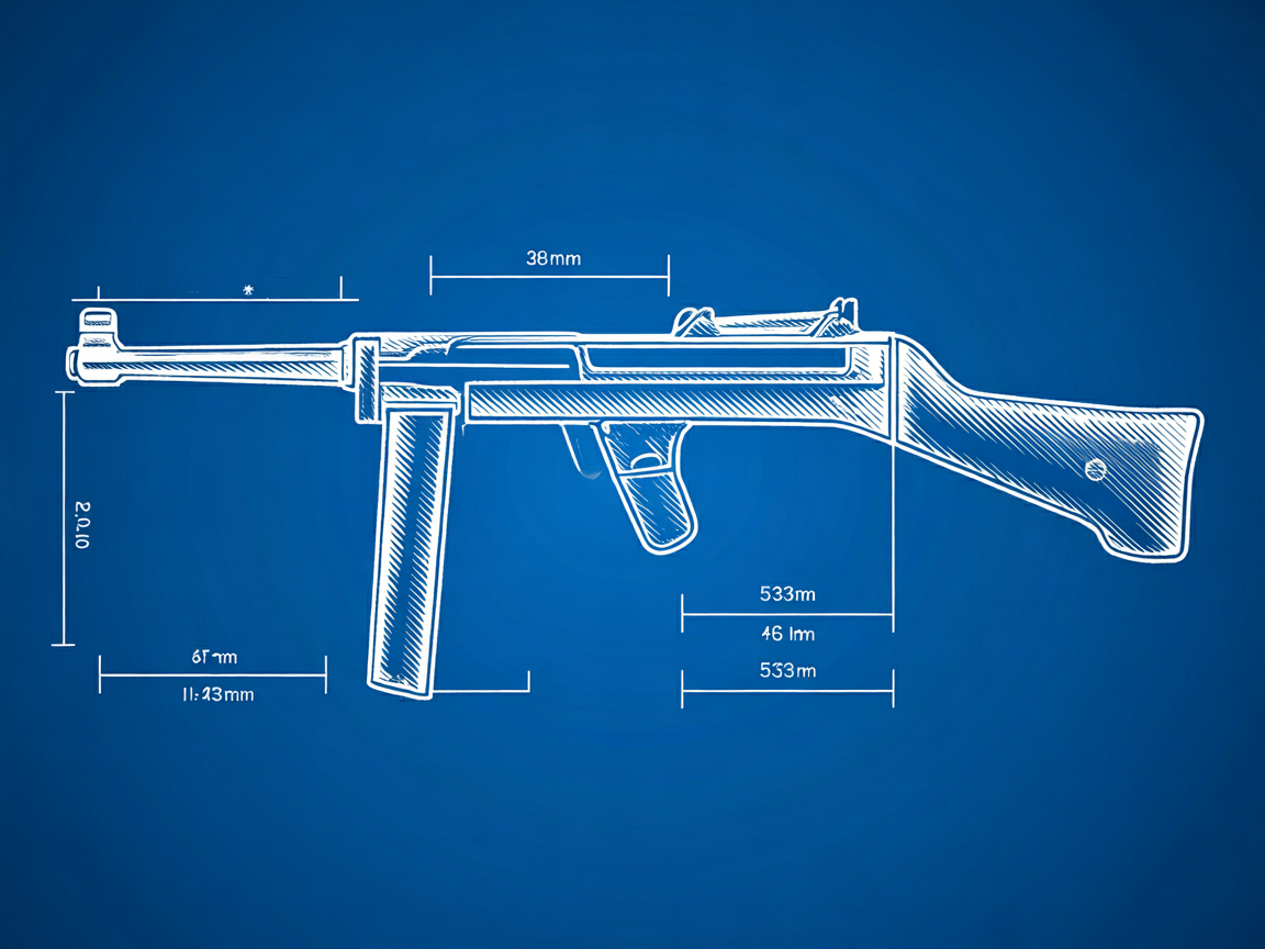
The receiver tube is the gun’s defining engineering element and the part the Vol 7 lab build spends the most time on. The 1941 design brief specified it explicitly as a wrapped-and-welded sheet-steel cylinder rather than a bored seamless tube — both because seamless-steel tube of the required diameter was already constrained material in 1941 (much was going to aircraft and naval ordnance) and because wrapped-and-welded production didn’t require specialty cutting tools and could be done in shops with sheet-metal presses and arc welders.
4.4.1 Geometry
The Mk II receiver is a cylinder of ~38 mm (1.50″) outside diameter and ~533 mm (21.0″) length from the rear cap to the muzzle bushing. Wall thickness is ~2.0–2.5 mm (varies by factory; ROF Fazakerley ran slightly thinner, Long Branch slightly thicker — both within the MoS drawing tolerance). The cylinder is wrapped from a single sheet of low-carbon steel approximately 125 mm (4.9″) wide × 533 mm long, rolled into a cylinder, and butt-welded along a single longitudinal seam.
Where the seam goes is load-bearing. The UK MoS drawing for the Mk II receiver specifies the seam at the top of the receiver tube, oriented to the gun’s left (such that the bolt’s wear surfaces and the magazine well attachment both clear the seam). Modern garage fabrication sometimes places the seam at the bottom (so the eye doesn’t see it from the right-hand-shooter’s perspective) — this is mechanically equivalent but cosmetically non-original. The Professor Parabellum Vol III drawings specify the seam at the top-left per the MoS original.
The receiver tube has six major machined features after wrapping and welding:
- Magazine-well attachment slot on the left side — a rectangular cutout, ~60 mm × 30 mm, where the magazine well housing is welded onto the receiver. Located approximately 220 mm forward of the rear cap.
- Ejection port on the right side — a rectangular cutout, ~55 mm × 24 mm, opposite the magazine well. Same fore-aft location.
- Cocking-handle slot on the right side, upper rear — a longitudinal slot ~110 mm long × 8 mm wide that the cocking handle rides in. Starts approximately 50 mm aft of the ejection port and runs rearward.
- Trigger group housing attachment on the underside — typically two bolt-pass-through holes for the M5 (or 1/4″-28) bolts that retain the trigger group housing. Located approximately at the magazine-well fore-aft position.
- Buttplate-cap attachment at the rear — typically a threaded cap (left-hand thread; the cap unscrews counter-clockwise from the rear perspective, which is the opposite of standard right-hand thread to discourage accidental loosening from bolt-cycle vibration) or a pinned cap depending on factory.
- Muzzle bushing at the front — a threaded or pinned bushing that retains the barrel; the bushing has its own threaded interface to the receiver tube.
4.4.2 Material
Original Mk II receivers were 1020-1030 series low-carbon steel (the British equivalent was specified by tensile strength rather than alloy code, but the modern equivalent is in the SAE 1020-1030 range). The wartime spec called for 18-gauge or 16-gauge sheet depending on factory; modern reproductions standardize on 16-gauge (1.5 mm / 0.060″) or sometimes 14-gauge (1.9 mm / 0.075″) for a more-robust modern build.
Modern lab equivalent: 1018 or 1020 cold-rolled sheet at 0.060″ (1.5 mm) is the canonical Vol 7 spec. Hot-rolled sheet works for the receiver tube but the surface finish is rougher (period-correct for a Mk II, but harder to weld cleanly). The Professor Parabellum Vol III drawings call for 1018 CR; this deep dive’s Vol 7 specifies the same.
4.4.3 Manufacturing in 1941 vs in the modern home lab
Table 4 — 4.3.3 Manufacturing in 1941 vs in the modern home lab
| Step | WWII RSAF / Fazakerley method | Home-lab method (Vol 7) |
|---|---|---|
| Cut sheet to size | Hand-shear or kick-shear | CNC plasma or CNC laser (a 100 W laser cutter is over-capable here) |
| Roll into cylinder | Three-roll bench bender | Sheet-metal roller (manual or CNC) |
| Butt-weld longitudinal seam | Manual arc weld (stick) | TIG weld with backing strip + post-weld stress relief |
| Machine cutouts (mag well, port, cocking slot) | Jig-mounted milling on a horizontal mill | CNC mill with custom fixture (the laser can cut some of these as an alternative) |
| Drill trigger-group attachment holes | Drill press with jig | Drill press or CNC mill |
| Thread or pin muzzle bushing + rear cap | Lathe-turn the bushings, hand-fit | Lathe-turn the bushings, machine-fit |
| Surface finish | Parkerize or oil black; sometimes paint | Parkerize, hot blue, or Cerakote (Vol 9) |
The lab build is faster and more precise than the WWII production because the CNC and laser can cut all the machined features in a single setup, while the wartime production split each feature across a separate purpose-built jig at a separate factory station. The 1941 production rate at Fazakerley was 47,000 Mk IIs per week (one every 12 seconds); a Vol 7 lab build is one receiver per shop-day or two with all the side-tasks. The advantage of the 1941 method was parallelism across hundreds of guns; the advantage of the lab method is flexibility and precision on a single build.
4.5 The bolt and the fixed firing pin
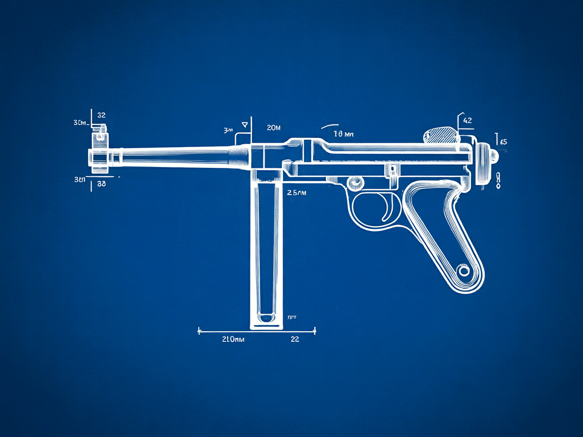
The Mk II bolt is the gun’s second-most-defining engineering element. It is a single lathe-turned part — no separate firing pin, no firing-pin spring, no firing-pin retainer — and that integration is the single largest cost-saving and reliability-improving choice in the entire 1941 design brief.
4.5.1 Geometry
The bolt is a cylinder of ~32 mm (1.26″) outside diameter sliding inside the ~38 mm ID receiver tube, with a ~3 mm radial clearance (so the bolt rides on the inside of the tube without binding, with debris-clearance tolerance for sand and field-dirt). The bolt’s overall length is ~210 mm (8.27″) including the rear portion that engages the recoil spring. The bolt has the following primary features:
- Bolt face at the front — a flat surface perpendicular to the bolt axis, machined to engage the 9×19 cartridge head. The firing pin is a small protrusion at the center of the bolt face, machined as part of the bolt (not a separate part). Diameter of the firing-pin protrusion is approximately 2.0 mm; protrusion above the bolt face is approximately 1.4 mm (enough to indent and fire a 9×19 primer, not enough to penetrate the primer cup).
- Extractor slot at the front — a longitudinal slot in the bolt face’s perimeter that holds the spring-loaded extractor claw. The extractor itself is a separate part (a small bent-spring-steel claw), pinned into the slot.
- Cocking handle pin hole on the right side — a transverse pinned attachment where the external cocking handle (a knob) is retained. The cocking handle pin is approximately 6 mm diameter.
- Sear engagement surface on the underside, near the rear — a flat surface that the trigger sear contacts to hold the bolt in the rearward (cocked) position when the gun is in the open-bolt full-auto-or-semi-auto state.
- Recoil spring guide at the rear — a turned-down section of smaller diameter that the recoil spring slides over.
4.5.2 The fixed firing pin and its consequences
The fixed firing pin (a machined protrusion of the bolt face, not a separate part) is the most-important single design choice in the gun. Its operational consequences:
- The bolt fires the cartridge by inertia, not by a separate firing-pin strike. The bolt slams forward under recoil-spring pressure, the bolt face strikes the cartridge primer with the bolt’s full mass, and the cartridge fires. There is no separate firing-pin-driving event.
- The gun is therefore an open-bolt gun by mechanical necessity. A closed-bolt design (where the bolt is forward at rest, with a cartridge chambered, and the firing event is triggered by a separate firing-pin strike) requires a separate firing pin and a firing-pin spring. The STEN’s fixed-firing-pin design cannot be a closed-bolt gun without redesign.
- ATF Rul. 83-5 (1983), which classifies the open-bolt, fixed-firing-pin YAC STEN MK II semi-auto carbine as a machine gun, therefore creates a Vol 7-specific challenge: a from-scratch lab build for the US market must implement a closed-bolt FCG that adds a separate firing pin to the bolt and a firing-pin striker mechanism to the FCG. The Professor Parabellum Vol III drawings include a closed-bolt FCG conversion approach; Vol 7 documents this as the canonical Vol 7 approach.
- No open-bolt semi-auto STEN is grandfathered. 83-5 contains no grandfather date (Correction, 2026-10-20: earlier versions said pre-1982 open-bolt semi-auto STENs were grandfathered under a “1982 rule”; ATF’s texts do not support that — Vol 10 § 10.4). A modern build cannot use the open-bolt design; a builder who wants an open-bolt STEN must go Path A (NFA Class III pre-86 transferable, which is a full-auto gun by registration).
- Drop-fire risk is real on an open-bolt gun: if the gun is dropped on the buttplate with the bolt unsecured, the bolt can slide forward under inertia and fire a chambered cartridge. The WWII Mk II safety (a slot in the receiver that holds the cocking handle) is famously inadequate. The Mk V safety is improved. The closed-bolt Vol 7 design eliminates this entirely.
4.5.3 Material
The bolt is medium-carbon steel — SAE 4140 in modern equivalent, case-hardened at the bolt face and the firing-pin protrusion. The case-hardening depth at the bolt face is approximately 0.5–1.0 mm with a surface hardness of Rc 55–58; the bolt body interior remains tough (~Rc 30) to handle the impact loading of the blowback cycle.
Modern lab equivalent: 4140 round stock at ~32 mm diameter, lathe-turned to the bolt geometry, with the bolt face and firing-pin protrusion case-hardened post-machining via either a pack-carburizing or a salt-bath carburizing process (a gunsmith specialty; Vol 9 covers the process options). The Professor Parabellum Vol III drawings specify 4140.
4.6 The trigger group housing — FCG
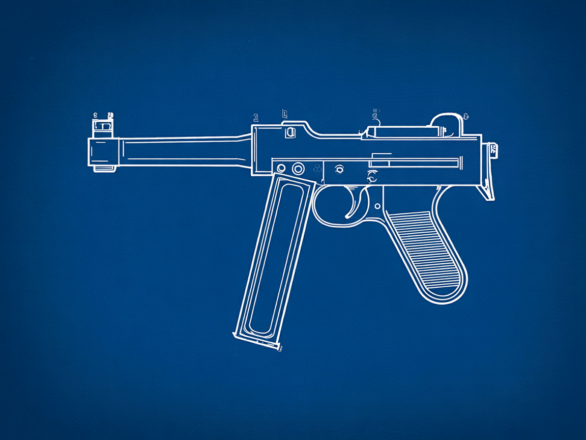
The trigger group housing (often called the FCG, fire control group housing) is the bottom-mounted sub-assembly that contains the trigger, sear, magazine well, and pistol grip (or pistol-grip-stub on the Mk II). The Mk II’s trigger group housing was stamped sheet steel at most UK factories; the Long Branch (Canadian) production used cast aluminum from the start; some late-war UK production also moved to cast aluminum. The Mk V’s housing is a more-elaborate machined or cast unit with an integral pistol grip.
4.6.1 Mk II stamped-sheet housing
The stamped Mk II housing is fabricated from 18-gauge or 16-gauge sheet (factory-specific), folded into a U-shape with the magazine-well slot at the front and the trigger guard at the rear, and welded or riveted along the bottom seam. The magazine well projects forward at the front of the housing as a rectangular tube perpendicular to the receiver-tube axis. The trigger guard is integral to the bottom-rear of the housing.
The internal mechanism (trigger, sear, sear spring, disconnector, magazine-catch, fire-mode selector for the original full-auto/semi-auto gun) is pinned together with small-diameter steel pins (~2.5 mm) running transversely through the housing. The fire-mode selector on a WWII Mk II is a simple side-mounted switch that engages or disengages the disconnector — for full-auto, the disconnector is disabled (the trigger holds the sear down continuously); for semi-auto, the disconnector resets the sear after each shot.
For a Vol 7 build, this housing is reworked as a closed-bolt semi-auto-only FCG. The disconnector is repurposed to control the new firing-pin-strike mechanism rather than the bolt sear. The Professor Parabellum Vol III drawings provide the closed-bolt FCG layout.
4.6.2 Mk II cast aluminum housing (Long Branch and late UK)
The cast aluminum housing is mechanically equivalent to the stamped sheet but significantly cleaner-looking and dimensionally more consistent. The casting is post-machined to fit the internal mechanism. Long Branch’s cast housing has its factory codes (“L/B” or “LBL”) cast into the housing itself, making it the easiest variant to identify on a captured/surplus STEN.
For a Vol 7 lab build, CNC milling the housing from 6061-T6 aluminum bar is the modern equivalent of the wartime casting. It’s faster than casting (no foundry pattern, no cooling time, no cleanup of cast surface), more dimensionally precise, and gives a cleaner cosmetic result. The Professor Parabellum drawings allow either approach.
4.6.3 Mk V housing
The Mk V housing is a fundamentally different design — machined from a steel forging, with an integral pistol grip (the Mk II has only a pistol-grip-stub and the user grips the housing itself; the Mk V has a real pistol grip with wooden grip panels). The Mk V housing also includes the bayonet lug at the muzzle (welded to the muzzle bushing rather than to the housing, but visually associated with the front of the gun).
For a Vol 7 stretch build targeting the Mk V configuration, the housing requires significantly more machining time than the Mk II. The CNC mill operations are straightforward but multi-setup (the pistol grip projects below the magazine-well, requiring a fixture rotation between operations). Vol 7’s primary target is Mk II; Mk V is a follow-on build documented as a delta.
4.7 The barrel and chamber
The Mk II barrel is 197 mm (7.75″) long, 9×19 chambered, .355″ (9.0 mm) bore, 4-groove (some sources cite 6-groove for late-war production), 1:10 inch right-hand twist. The barrel is a low-pressure pistol-class barrel — 9×19 peak pressure is ~35,000 psi SAAMI (vs ~62,000 psi for 5.56 NATO and ~58,000 psi for 7.62 NATO) — and the wall thickness is modest (~2.5 mm).
4.7.1 Retention
The barrel is retained in the receiver by the muzzle bushing: the bushing threads or pins to the receiver tube and clamps the barrel from the muzzle end. The breech end of the barrel sits in a chamber boss machined into the receiver-tube interior; the chamber boss locates the barrel and aligns it with the bolt axis. There is no separate barrel nut or barrel extension; the bushing-and-boss combination is sufficient for the 9×19 pressure regime.
4.7.2 Lab build options
A Vol 7 builder has two paths for the barrel:
- Buy a pre-rifled barrel blank from a US barrel-blank vendor (E.R. Shaw, Green Mountain, Bear Creek Arsenal, McGowen, McCory, or a custom barrel maker like Krieger or Bartlein for the Mk V stretch build). The blank arrives un-chambered; the builder cuts the chamber in-lab with a 9×19 chamber reamer (a stock SAAMI-spec reamer; Brownells / PTG / Manson all sell them at ~$200) and cuts the muzzle to length with the bushing fit. Recommended approach — the barrel is the only Vol 7 part where farming out the manufacturing is reasonable, and the rifling is the only operation where the lab can’t easily match commercial quality.
- Rifle in-house using button rifling, single-point cut rifling, or EDM rifling. Possible with appropriate fixtures — the 4-groove .355″ rifling is among the simplest rifling jobs in the firearms world (pistol-class bore, short barrel, conventional groove geometry) — but adds significant fixture-build time. A CNC and 3D-printer setup can produce the rifling tooling; the question is whether it’s worth the build-time investment. For a one-off Mk II build, option 1 is recommended. For a multi-build trajectory, option 2 becomes interesting because amortizing the rifling-fixture build across multiple barrels makes the per-barrel cost approach zero.
4.7.3 Chamber dimensions
The 9×19 chamber is SAAMI-spec for a modern lab build. The 1941 UK MoS drawing specifies a slightly tighter chamber (the British military 9×19 ammunition of the period was loaded to slightly tighter tolerances than commercial 9×19); modern commercial 9×19 ammunition will safely fire in either chamber, but a 1941-spec chamber may show slightly tight extraction with modern hot-loaded 9×19 (+P or +P+). For Vol 7, the SAAMI-spec chamber is the right choice — it has wider tolerance for ammunition variation and matches the modern commercial reamer market.
4.8 The magazine and the feed-lip pathology
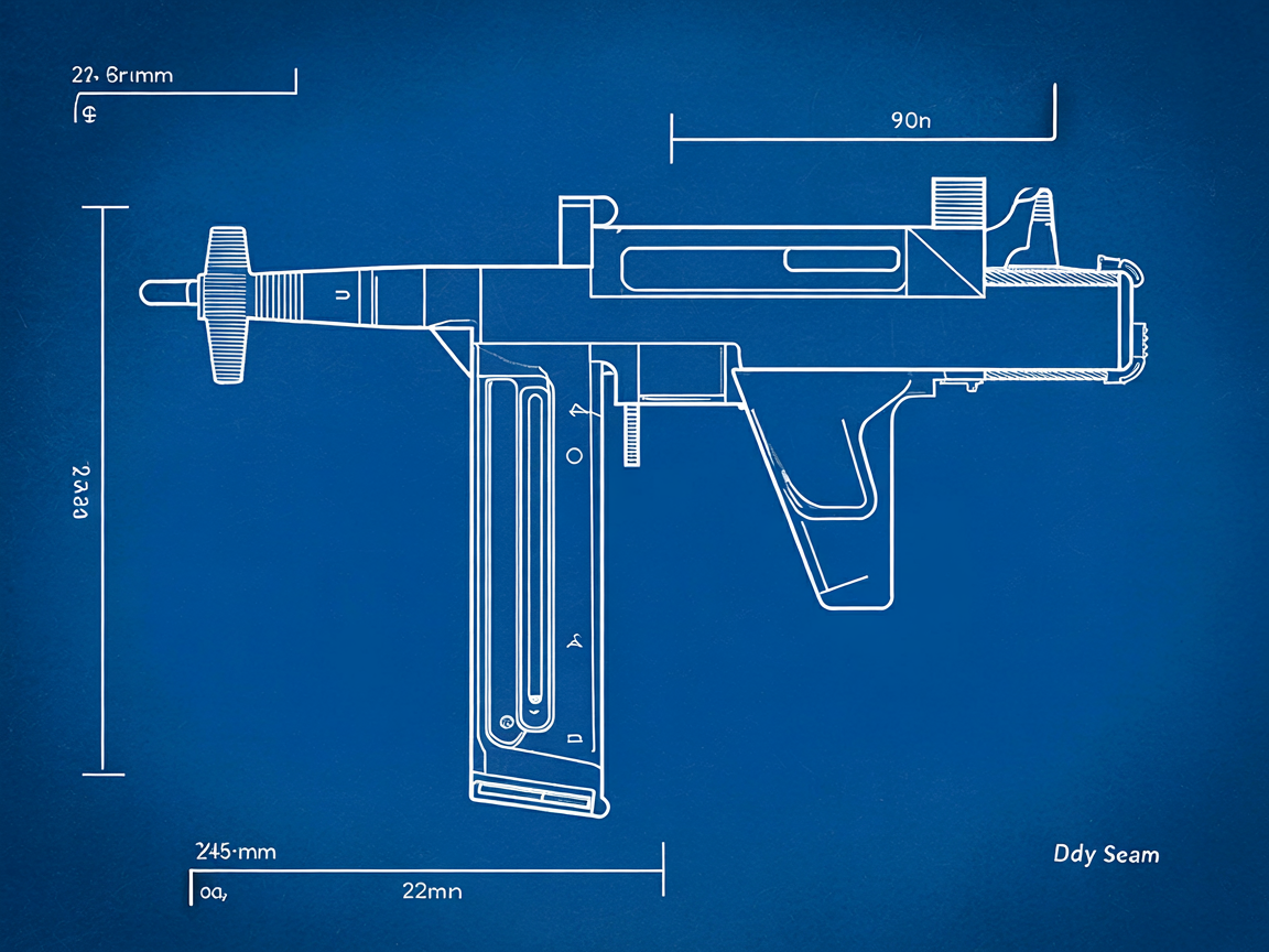
The Mk II magazine is the gun’s most-troubled element. It is a 32-round side-feed double-stack-to-single-feed magazine, sheet-steel construction, derived directly from the German MP 28 → Lanchester lineage. The 32-round capacity is what fits in the body length given the 9×19 cartridge geometry.
4.8.1 Geometry
The magazine body is approximately 245 mm (9.65″) long × 32 mm (1.26″) wide × 22 mm (0.87″) deep, with a slight curve (banana profile) along its length to suit the 9×19’s slight taper. The body holds a double-stack column for most of its length, narrowing to a single-feed at the top where the cartridge presents to the bolt face.
The body has the following features:
- Feed lips at the top — bent-in steel that retains the top cartridge in single-feed position and presents it to the bolt face. The feed-lip geometry is the single most-critical dimension in the magazine and is the subject of the gun’s most-notorious reliability problem.
- Follower spring — a long flat coil spring inside the body that pushes cartridges upward.
- Follower — a sheet-metal plate that rides the spring and pushes the cartridge stack upward.
- Floor plate at the bottom — a removable plate (slid in by a longitudinal lug system) that retains the spring and follower.
- Body seam along the rear edge (the magazine’s “back”) — typically welded or spot-welded.
4.8.2 The feed-lip pathology
The Mk II magazine’s notorious problem: the feed lips are insufficiently work-hardened for sustained use, and they deform under repeated loading-and-firing cycles. Once the feed lips deform, the magazine:
- presents cartridges at the wrong angle to the bolt face → feed jam (cartridge nose strikes the chamber mouth rather than entering the chamber);
- releases cartridges before the bolt face is in position to catch them → dropped round during cycling (cartridge falls out of the gun, often visibly);
- presents two cartridges simultaneously → double-feed jam.
The WWII solution was simply to replace magazines every few hundred rounds of full-auto use. The reason this problem persisted is that fixing it (a thicker feed-lip section, or a heat-treated feed-lip insert) would have added cost the 1941 brief did not allow.
For a modern Vol 7 build, the feed lips of any magazine are the first thing to inspect and true. Surplus STEN magazines are still sold (Apex Gun Parts listed 32-round steel magazines in Fair condition at $19.95 on 2026-10-18), but no newly made US STEN magazine was found in a 2026-10-18 search of the maker and dealer pages. The practical answer is to buy several surplus magazines, gauge and true their feed lips, and keep the best ones as the working set (Vol 11 § 11.3). Whether a Sterling magazine will feed reliably in a Mk II was not confirmed from any maker’s or armourer’s source for this dive.
4.8.3 Material
Original Mk II magazines: low-carbon steel sheet, ~0.030″ (0.75 mm) wall, unhardened feed lips, oil-blacked surface. Modern Sterling-pattern magazines: medium-carbon spring steel, ~0.030″ (0.75 mm) wall, hardened feed lips (Rc 45–50), parkerized or anodized surface.
4.9 The stock variants
Three stock variants matter for the modern build:
- Mk II skeleton T-frame — two pieces of welded steel rod (~9.5 mm / 3/8″ diameter), forming an inverted-T against the shoulder. Detachable from the receiver via a lug-and-cross-pin. Iconic; the visual silhouette most people associate with “STEN”.
- Mk II wire-loop — a single piece of bent steel rod forming a closed-loop oval against the shoulder. Some late-war and Long Branch Mk IIs used this instead of the T-frame; mechanically equivalent, slightly more shoulder-friendly.
- Mk V wooden buttstock + foregrip — full-length hardwood (beech or walnut depending on factory) with a steel-cup buttplate and a hardwood foregrip under the barrel. The Mk V foregrip eliminates the Mk II grasp-the-magazine pathology (Vol 11 § 11.3). Recommended for a Vol 7 Mk V stretch build.
The skeleton T-frame is the easiest stock to fabricate (two pieces of bent steel rod, welded together — an hour on the welding bench, less with a jig). The Mk V wooden stock is a CNC-router job (~2 hours for the buttstock, ~1 hour for the foregrip) plus surface finishing.
4.10 Materials — period steel grades and modern equivalents
A consolidated materials table for the Vol 7 builder:
Table 5 — A consolidated materials table for the [Vol 7](/actual-firearms/rifles/sten-gun/vol-7/) builder
| Part | WWII material (best modern equivalent) | Recommended material for Vol 7 build |
|---|---|---|
| Receiver tube | Low-carbon sheet (SAE 1020-1030 equiv) | 1018 or 1020 cold-rolled sheet, 0.060″ (1.5 mm) |
| Bolt | Medium-carbon (SAE 4140 equiv), case-hardened bolt face | 4140 round stock, ~32 mm dia, case-hardened post-machining |
| Trigger group housing (Mk II stamped) | Low-carbon sheet (~16 gauge) | 16-gauge 1018 mild steel sheet |
| Trigger group housing (Mk II cast aluminum) | Cast aluminum (period equivalent of 6061-class) | 6061-T6 aluminum bar, CNC-milled |
| Trigger group housing (Mk V steel forging) | Carbon steel forging | 1045 or 4140 bar, CNC-milled |
| Internal mechanism parts (trigger, sear, disconnector, magazine catch) | Low-carbon stamped steel, surface-hardened | 4140 bar stock, machined, case-hardened |
| Springs (FCG, recoil, magazine) | Spring steel | Music wire (ASTM A228), commercial spring suppliers |
| Barrel | Medium-carbon (proof-tested) | 4150 chrome-moly barrel blank (pre-rifled) |
| Stock (Mk II rod) | Mild steel rod | 1018 round bar, ~9.5 mm (3/8″) |
| Stock (Mk V wood) | Beech or walnut | Walnut or maple hardwood blank |
| Magazine body | Low-carbon spring steel | (Use commercial Sterling-pattern aftermarket; do not fabricate) |
4.11 Surface treatments — period and modern
Period-correct: parkerized (zinc or manganese phosphate, dark gray-green to nearly black) was the canonical Mk II finish; some late-war Mk IIs were oil-blacked (a simpler dip process); some emergency-production Mk IIs and Mk IIIs were suncorite-painted (a heat-cured black paint, the period equivalent of modern Cerakote in color and durability). The Mk V was always parkerized; the wood was oiled with linseed or boiled linseed oil.
Modern Vol 7 options (Vol 9 covers each in detail):
- Parkerizing — manganese phosphate is the period-correct choice; zinc phosphate is a paler alternative. Both are easy to do in a lab tank.
- Hot blue — more durable than parkerizing, glossy black, requires a hot-blue tank setup. Not period-correct for a Mk II.
- Cerakote — modern ceramic coating, extremely durable, available in matte black to match period parkerizing or in any other color. Easy to apply with a small cure oven.
- Suncorite paint or equivalent — period-correct alternative for a Mk III-style “even cheaper” finish.
For a Mk II Vol 7 build, manganese phosphate parkerizing is the recommended period-correct finish. For a Mk V Vol 7 build, parkerizing on the metal + boiled linseed oil on the wood matches the wartime spec.
4.12 References (Vol 4)
- UK Ministry of Supply. Drawing list for Carbine, Machine, 9 mm STEN Mk I / Mk II / Mk III / Mk V / Mk VI. SA-prefix drawing numbers; National Archives Kew (WO 185, SUPP 5, AVIA 22 series); Royal Armouries Leeds. Crown Copyright, Open Government Licence v3.0.
- Skennerton, Ian. The Sten Machine Carbine. (Variant catalog with engineering summaries; cites the MoS drawings extensively.)
- Iannamico, Frank. The STEN Submachine Gun. (Moose Lake Publishing, multiple editions; deep engineering content per Mark.)
- Hogg, Ian V., and John Weeks. Military Small Arms of the 20th Century. (General reference; per-Mk dimensioned summaries.)
- Professor Parabellum. Practical Scrap Metal Small Arms, Volume III: The DIY STEN Gun. (Wikimedia Commons, CC BY 1.0 PDF — the canonical modern reverse-engineered drawings + op-sequence treatment. Note: prior versions of Vols 1 + 2 of this deep dive incorrectly cited “Vol I” as the STEN treatment; Vol III is the correct STEN-specific volume — errata noted in the volume-source notes.)
- Apex Gun Parts. STEN parts kit technical sheets + 922(r) compliance documentation. (Vendor reference; cited in Vol 6.)
- US Foreign Science and Technology Center. FSTC 381-5012 — Typical Foreign Unconventional Warfare Weapons (U). US-government work product, public domain; available on Wikimedia Commons as a 783×1250 PDF.
- US Army John F. Kennedy Center for Special Warfare. US Army Special Forces Foreign Weapons Handbook. 1967. DTIC AD0867982. (US-government work product, public domain; Mark V STEN entry.)
- Office of Strategic Services. Military Equipment and Supplies for Guerrilla Operations / Production of STEN Submachine Guns and Ammunition in the U.S. 1942. CIA CREST CIA-RDP13X00001R000100300008-3. (US-government work product, public domain.)
- The National Archives Kew. STEN design, contract and trials files in AVIA 22, WO 185, WO 291 and other series; no catalogued drawing set. File references and ordering in § 4.1.5.
- The Royal Armouries Leeds. Archives of the Royal Small Arms Factory (Enfield) and the MOD Pattern Room; STEN drawing holdings to be confirmed with the archivist (§ 4.1.5).
- The Imperial War Museum Duxford. WWII production-history material including some STEN engineering files.
Comments (0)